RealView Logic Tile
F-4 Copyright © 2003-2007 ARM Limited. All rights reserved. ARM DUI 0224F
F.3 Header connectors
This section gives an overview of the RealView Logic Tile header connectors on the
PB926EJ-S. For more detail, see the documentation for your RealView Logic Tile.
There are three headers on the top and bottom of the tile. The HDRX and HDRY
headers are 180-way and the HDRZ connectors are 300-way.
Warning
There is a limit to the number of RealView Logic Tiles which can be stacked on a
RealView baseboard. For the PB926EJ-S the recommended limit is two.
When stacking tiles ensure that the power source can maintain the required voltage at
the top tile when supplying maximum current to the system. If necessary, use a seperate
bench supply or power the system from a PCI backplane. See Current requirements
from J34 on page B-3 for further details.
Caution
The FPGA signals on a RealView Logic Tile and the PB926EJ-S are fully
programmable. Ensure that there are no clashes between the signals on the tiles or with
the signals from the PB926EJ-S.
The FPGA can be damaged if several pins configured as outputs are connected together
and attempt to output different logic levels.
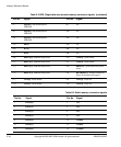
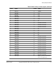
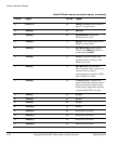
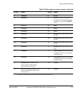
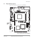
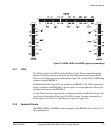
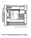
Figure F-3 on page F-5 shows the pin numbers and power-blade usage of the HDRX,
HDRY, and HDRZ headers on the upper side of the tile. See RealView Logic Tile header
connectors on page A-17 for details of the signals on the PB926EJ-S header connectors.


