


Hardware Description
ARM DUI 0224F Copyright © 2003-2007 ARM Limited. All rights reserved. 3-31
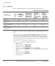
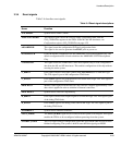
nPWRFAIL This signal is provided by the FPGA to the interrupt controller. User software can test
this signal and shut down before a power loss causes a loss of data.
Note
This signal is not driven by any power-detection logic. It is provided so that custom
implementations of the FPGA image have a signal that could be manipulated by a
register. Creating such an FPGA image would enable testing of user software that
implements a shutdown routine.
nRESET Reset signal to the development chip and FPGA. The CPU core, all system
peripherals, and some system controller registers are reset. This signal is synchronized
with the system bus clock to provide AMBA compliance. For details on system
registers reset at different reset levels, see Table 4-4 on page 4-18.
nSRST nSRST is an active LOW open-collector signal that can be driven by the JTAG
equipment to reset the board. Some JTAG equipment senses this line to determine
when you have reset a board.
This is also used in configuration mode to control the initialization of the FPGA.
Note
nSRST splits into D_nSRST and C_nSRST to provide separate debug and
configuration signals on the Logic Tile connector HDRZ.
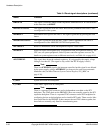
nSYSPOR Power-on reset signal that initializes the reset level state machine after
GLOBAL_DONE goes HIGH. This signal is also fed to a Logic Tile header.
nSYSRST System reset to the Logic Tile header. This signal is synchronized with the system bus
clock to provide AMBA compliance.
nTRST TAP controller reset (the board drives this signal with nBOARDPOR).
Note
nTRST splits into SDC_nTRST, D_nTRST, and C_nTRST to provide separate
debug and configuration signals on HDRZ of the Logic Tile.
USBnRESET System reset to USB controller.
USBWAKEUP Signal to USB controller to re-initialize.
Table 3-4 Reset signal descriptions (continued)
Name Function