


Programmer’s Reference
ARM DUI 0224F Copyright © 2003-2007 ARM Limited. All rights reserved. 4-55
4.9 Ethernet
The Ethernet interface is implemented in an external SMC LAN91C111 10/100
Ethernet single-chip MAC and PHY. The internal registers of the LAN91C111 are
memory-mapped onto the AHB M2 bus and occupy 16 word locations at
0x10010000
.
To access the PHY MII registers, you must implement a synchronous serial connection
in software to control the management register in Bank 3. By default, the PHY is set to
isolate in the control register. This disables the external interface. Refer to the
LAN91C111 application note or to the self test program supplied on the CD for
additional information.
When manufactured, an ARM value for the Ethernet MAC address and the register base
address are loaded into the EEPROM. The register base address is 0. The MAC address
is unique, but can be reprogrammed if required. Reprogramming of the EEPROM is
done through Bank 1 (general and control registers).
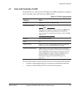
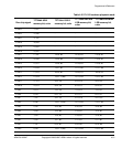
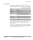
Table 4-35 Ethernet implementation
Property Value
Location Board (LAN91C111 chip)
Memory base address
0x10010000
Interrupt 25 on both the primary and secondary controllers
DMA None, use memory to memory DMA to access the buffer
memory. The master interface located in the LAN91C11 is not
supported.
Release version The FPGA contains a custom interface to the LAN91C111 chip
Reference documentation LAN91C111 Data Sheet (see also Ethernet interface on
page 3-68).