Stacking S-Series Switches | 1029
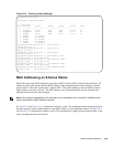
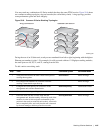
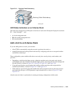
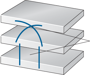
Figure 50-11. Stacking Cable Redundancy
LED Status Indicators on an S-Series Stack
The stack unit is displayed in an LED panel on the front of each switch. Each panel displays the stack unit
ID — from 0 through 7 — and:
• A for the management unit
• Bfor the standby management unit
• 0 for stack members
Add a Unit to an S-Series Stack
If you are adding units to a stack, you can either:
• allow FTOS to automatically assign the new unit a position in the stack, or
• manually determine each units position in the stack by configuring each unit to correspond with the
stack before connecting it
Three configurable system variables affect how a new unit joins a stack: priority, stack number, and
provision.
• Depending on which has the higher priority, either the standalone unit or the entire stack reloads
(excluding the new unit). If the new unit has the higher priority, it becomes the new stack manager and
the stack reloads, as shown in Figure 50-3, Figure 50-4, Figure 50-5, and Figure 50-6.
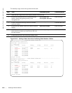
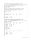
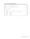
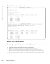
• If you add a unit that has a stack number that conflicts with the stack, the stack assigns the first
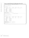
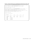
available stack number, as shown in Figure 50-12 and Figure 50-13.
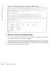
• If the stack has a provision for the stack-number that will be assigned to the new unit, the provision
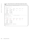
must match the unit type, or FTOS generates a type mismatch error, as show in Figure 50-14 and
Figure 50-15.
After the new unit loads, it synchronizes its running and startup configurations with the stack.
Stacking 002
A
B
A
B
A
B
Stacking Cable Redundancy


