336 | Force10 Resilient Ring Protocol
www.dell.com | support.dell.com
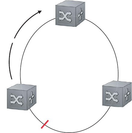
Each Transit node is also configured with a Primary port and a Secondary port on the ring, but the port
distinction is ignored as long as the node is configured as a Transit node. If the ring is complete, the Master
node logically blocks all data traffic in the transmit and receive directions on the Secondary port to prevent
a loop. If the Master node detects a break in the ring, it unblocks its Secondary port and allows data traffic
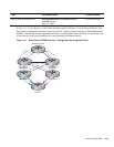
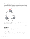
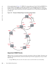
to be transmitted and received through it. See Figure 15-1 for a simple example of this FRRP topology.
Note that ring direction is determined by the Master node’s Primary and Secondary ports.
Figure 15-1. Normal Operating FRRP Topology
A Virtual LAN (VLAN) is configured on all node ports in the ring. All ring ports must be members of the
Member VLAN and the Control VLAN.
The Member VLAN is the VLAN used to transmit data as described earlier.
The Control VLAN is used to perform the health checks on the ring. The Control VLAN can always pass
through all ports in the ring, including the secondary port of the Master node.
Ring Status
The Ring Failure notification and the Ring Status checks provide two ways to ensure the ring remains up
and active in the event of a switch or port failure.
Ring Checking
At specified intervals, the Master Node sends a Ring Health Frame (RHF) through the ring. If the ring is
complete, the frame is received on its secondary port, and the Master node resets its fail-period timer and
continues normal operation.
Ring Direction
Primary
Forwarding
Primary
Forwarding
Secondary
Blocking
Primary
Forwarding
Secondary
Forwarding
Secondary
Forwarding
R2
TRANSIT
R3
TRANSIT
R1
MASTER


