


1128 | Virtual Router Redundancy Protocol (VRRP)
www.dell.com | support.dell.com
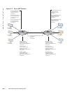
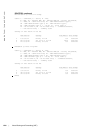
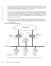
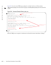
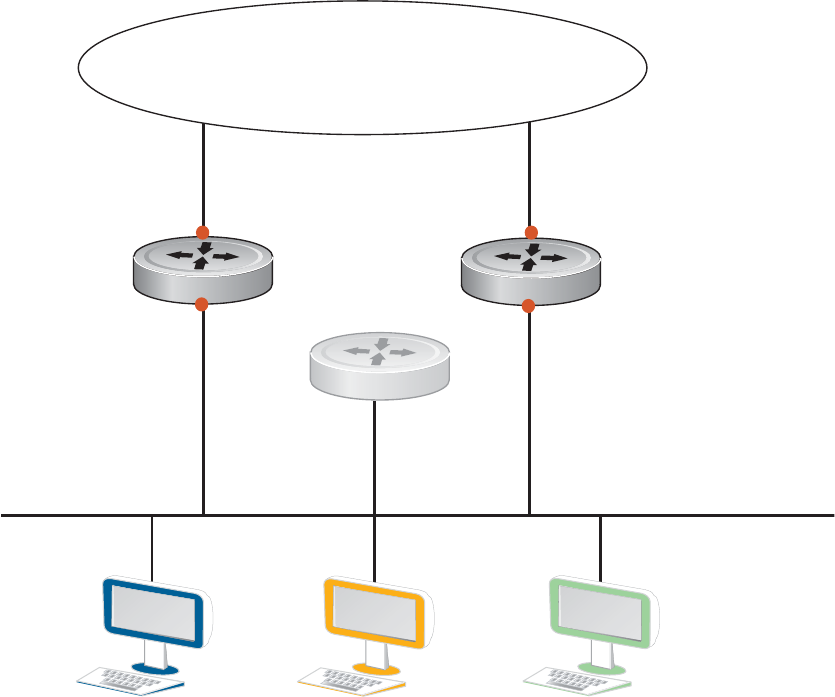
Figure 58-1 shows a typical network configuration using VRRP. Instead of configuring the hosts on the
network 10.10.10.0 with the IP address of either Router A or Router B as their default router; their default
router is the IP Address configured on the virtual router. When any host on the LAN segment wants to
access the Internet, it sends packets to the IP address of the virtual router.
In Figure 58-1 below, Router A is configured as the MASTER router. It is configured with the IP address
of the virtual router and sends any packets addressed to the virtual router through interface GigabitEthernet
1/1 to the Internet. As the BACKUP router, Router B is also configured with the IP address of the virtual
router. If for any reason Router A becomes unavailable, VRRP elects a new MASTER Router. Router B
assumes the duties of Router A and becomes the MASTER router. At that time, Router B responds to the
packets sent to the virtual IP address.
All workstations continue to use the IP address of the virtual router to address packets destined to the
Internet. Router B receives and forwards them on interface GigabitEthernet 10/1. Until Router A resumes
operation, VRRP allows Router B to provide uninterrupted service to the users on the LAN segment
accessing the Internet.
Figure 58-1. Basic VRRP Configuration
For more detailed information on VRRP, refer to RFC 2338, Virtual Router Redundancy Protocol.
10.10.10.4
10.10.10.5
10.10.10.6
10.10.10.0/24
LAN Segment
Interface gi 1/0
10.10.10.1
Virtual IP Address
10.10.10.3
Router A
Master Router
Virtual IP 10.10.10.3
Priority 255
Router B
Backup Router
Virtual IP 10.10.10.3
Priority 100
Interface gi 10/0
10.10.10.2
Interface gi 1/1
63.62.154.23
Interface gi 10/1
204.1.78.37
INTERNET
IP Addresses
Default Gateway
10.10.10.3 10.10.10.3 10.10.10.3
FN0001_lp
Virtual Router