


548 | Link Aggregation Control Protocol
www.dell.com | support.dell.com
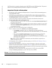
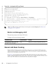
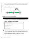
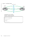
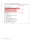
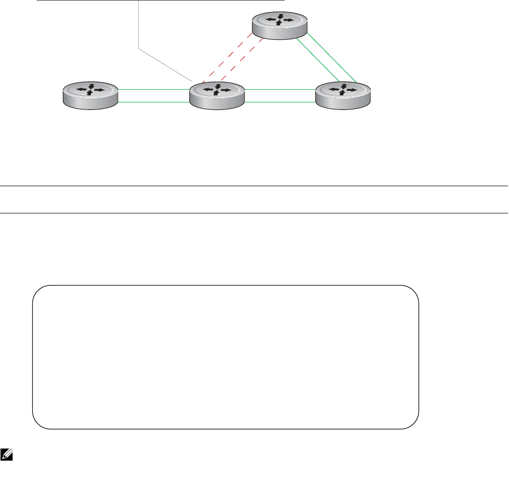
In Figure 24-8, LAGs 1 and 2 are members of a failover group. LAG 1 fails and LAG 2 is brought down
upon the failure. This effect is logged by Message 2, in which a console message declares both LAGs
down at the same time.
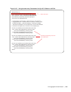
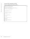
Figure 24-8. Shared LAG State Tracking
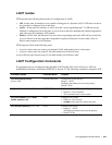
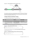
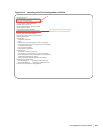
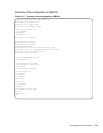
View the status of a failover group member using the command show interface port-channel, as shown in
Figure 24-9.
Figure 24-9. Viewing Status of a Failover Group Member
Important Points about Shared LAG State Tracking
• This feature is available for static and dynamic LAGs.
Message 2 Shared LAG State Tracking Console Message
2d1h45m: %RPM0-P:CP %IFMGR-5-OSTATE_DN: Changed interface state to down: Po 1
2d1h45m: %RPM0-P:CP %IFMGR-5-OSTATE_DN: Changed interface state to down: Po 2
Note: The set of console messages shown in Message 2 appear only if Shared LAG State Tracking is
configured on that router (the feature can be configured on one or both sides of a link). For example, in
Figure 24-8, if Shared LAG State Tracking is configured on R2 only, then no messages appear on R4
regarding the state of LAGs in a failover group.
Po 1
Po 2
fnC0049mp
R1
R2 R3
R4
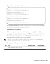
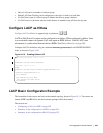
R2(conf)# port-channel failover-group
R2(conf-po-failover-grp)# group 1 port-channel 1 port-channel 2
R2#show interface Port-channel 2
Port-channel 2 is up, line protocol is down (Failover-group 1 is down)
Hardware address is 00:01:e8:05:e8:4c, Current address is 00:01:e8:05:e8:4c
Interface index is 1107755010
Minimum number of links to bring Port-channel up is 1
Port-channel is part of failover-group 1
Internet address is not set
MTU 1554 bytes, IP MTU 1500 bytes
LineSpeed 1000 Mbit
Members in this channel: Gi 1/17(U)
ARP type: ARPA, ARP Timeout 04:00:00
Last clearing of "show interface" counters 00:01:28
Queueing strategy: fifo