Intel
®
IXP42X product line and IXC1100 control plane processors—PCI Controller
Intel
®
IXP42X Product Line of Network Processors and IXC1100 Control Plane Processor
DM September 2006
234 Order Number: 252480-006US
6.7 PCI Controller Functioning as Bus Target
The IXP42X product line and IXC1100 control plane processors can be the target of PCI
transactions. Operating as a PCI target, the PCI bus can accept Memory Cycles, I/O
Cycles, or Configuration Cycles. Target transactions can take place independent of the
Host/Option configuration of the IXP42X product line and IXC1100 control plane
processors. Please refer to Table 97, “PCI Target Interface Supported Commands” on
page 211 for additional information on supported commands.
Only Type 0 Configuration Cycles are supported.
Timing diagrams are not shown for the target transactions because they are similar to
initiated transactions. The only differences are the PCI devices that source/sink the
various PCI signals.
For target-read transactions, a retry will be issued upon the IXP42X product line and
IXC1100 control plane processors receiving a request to transfer data. Between the
time that the retry occurs and the access to the IXP42X product line and IXC1100
control plane processors reoccurs, the PCI Controller on the IXP42X product line and
IXC1100 control plane processors retrieve the data from the previously requested
location.
For additional details, see the PCI Local Bus Specification, Rev. 2.2.
6.8 PCI Controller DMA Controller
The IXP42X product line and IXC1100 control plane processors contain two channels
that can be used for DMA (Direct Memory Accesses) to/from the PCI bus and the AHB.
The DMA Controller function provides two channels of DMA capability to off load, from
the Intel XScale processor, large data transfers between the PCI bus and AHB.
The DMA channels are unidirectional: one DMA channel is used for PCI-to-AHB transfers
and one DMA channel is used for AHB-to-PCI transfers. The DMA transfers are
implemented using three of the PCI Controller Configuration and Status Registers to
specify the PCI address, the AHB address, and the transfer length. Each DMA channel
has two sets of three registers to provide buffering for consecutive transfers.
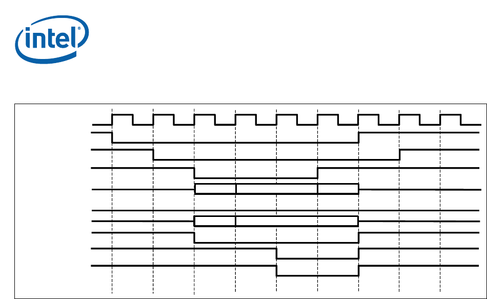
Figure 44. Initiated PCI Burst Memory Write Cycle
PCI_CLK
PCI_FRAME_N
PCI_AD (31:0)
PCI_IDSEL
PCI_C/BE_N
PCI_IRDY_N
PCI_TRDY_N
PCI_DEVSEL_N
0x00000014 DATA 0
0x7 0x0
INT_REQ_N
INT_GNT_N
DATA 1


