Intel
®
IXP42X Product Line of Network Processors and IXC1100 Control Plane Processor
September 2006 DM
Order Number: 252480-006US 545
UTOPIA Level-2—Intel
®
IXP42X product line and IXC1100 control plane processors
In cell-level single-PHY (SPHY) mode, the physical interface indicates that a cell is
ready to be sent by asserting the UTP_IP_FCI (a.k.a. RX_EMPTY_N/RX_CLAV) signal.
The UTOPIA Level-2 Interface on the IXP42X product line and IXC1100 control plane
processors subsequently initiates the transfer of a cell from the physical interface by
asserting UTP_IP_FCO (a.k.a. RX_ENB_N).
In octet-level single-PHY (SPHY) mode, the UTOPIA Level-2 Interface on the IXP42X
product line and IXC1100 control plane processors indicate to the physical interface
that the UTOPIA Receive interface is ready to receive bytes by asserting UTP_IP_FCO
(a.k.a. RX_ENB_N) signal. The physical interface indicates a valid byte is on the
UTOPIA data bus by de-asserting UTP_IP_FCI (also known as RX_EMPTY_N/RX_CLAV)
signal.
The Receive Module maintains various statistical counters. The statistics that can be
maintained are on a single physical port address on a specified VPI/VCI address value.
The 32-bit counters will maintain the following counts:
• The number of cells received
• The number of cells with an incorrect cell size
• The number of cells containing HEC errors.
• The number of idle cells received
The counters are not cleared when read by the Network Processor Engine core. The
Network Processor Engine core must perform an explicit write to the specified register
to clear the counter values.
There is an overflow bit per counter to indicate that the count has “rolled over.” A mask-
able interrupt mechanism is used to allow the UTOPIA Level-2 Coprocessor to flag to
the Network Processor Engine Core that a “roll over” has occurred.
19.3 UTOPIA-2 Coprocessor / NPE Coprocessor: Bus Interface
The Network Processor Engine Coprocessor Interface Module provides the necessary
interface logic required for configuration, monitoring, control, and test of the UTOPIA
Level-2 coprocessor. All of the UTOPIA Level-2 coprocessor’s internal configuration and
control registers, instruction registers, and FIFOs are directly accessible by the Network
Processor Engine core.
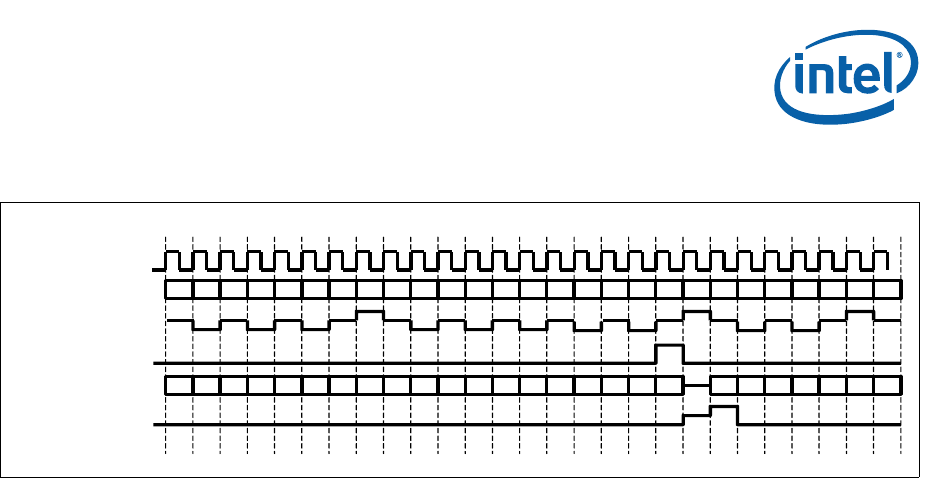
Figure 99. UTOPIA Level-2 MPHY Receive Polling
UTP_RX_CLK
UTP_RX_ADDR (4:0)
UTP_RX_FCI
(a.k.a. – RX_CLAV)
UTP_RX_FCO
(a.k.a. – RX_ENB_N)
UTP_RX_DATA(7:0)
UTP_RX_SOC
53
5251494847464544
43
4241403938 37 3635 65 4 3 2 1 7
50
0 1 2 3 4 5 6 7 8 9 10 11 12 13 14 15 16 17 18 19 20 21 22 24 25 26 27
A
C B
A
H
G
F E
D
D
H
G
E F


