


©2008 Advanced Micro Devices, Inc.
SMBus Module and ACPI Block (Device 20, Function 0)
AMD SB600 Register Reference Manual Proprietary Page 135
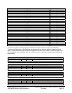
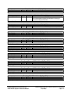
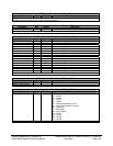
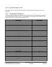
NCP_Error - RW – 8 bits - [IO_Reg: F0h]
Field Name Bits Default Description
NCP_Error register: In addition to the WarmBoot function, writing to this port will assert IGNNE# if FERR# is true. If
FERR# is false, then write to this port will not assert IGNNE#.
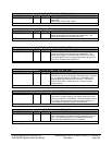
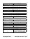
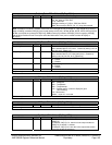
DMA1_Extend - RW – 8 bits - [IO_Reg: 40Bh]
Field Name Bits Default Description
DMA1_Extend 7:0 00h DMA1 extended write mode register
DMA1_Extend register
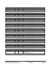
IntrEdgeControl- RW – 16 bits - [IO_Reg: 4D0h]
Field Name Bits Default Description
IRQ0Control 0 0b 1 = Level, 0 = Edge
IRQ1Control 1 0b 1 = Level, 0 = Edge
Reserved 2 0b
IRQ3Control 3 0b 1 = Level, 0 = Edge
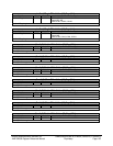
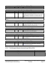
IRQ4Control 4 0b 1 = Level, 0 = Edge
IRQ5Control 5 0b 1 = Level, 0 = Edge
IRQ6Control 6 0b 1 = Level, 0 = Edge
IRQ7Control 7 0b 1 = Level, 0 = Edge
IRQ8Control 8 0b (Read Only) Always edge
IRQ9Control 9 0b 1 = Level, 0 = Edge
IRQ10Control 10 0b 1 = Level, 0 = Edge
IRQ11Control 11 0b 1 = Level, 0 = Edge
IRQ12Control 12 0b 1 = Level, 0 = Edge
Reserved 13 0b
IRQ14Control 14 0b 1 = Level, 0 = Edge
IRQ15Control 15 0b 1 = Level, 0 = Edge
IntrEdgeControl register: This register programs each interrupt to be either edge or level sensitive.
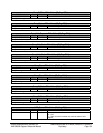
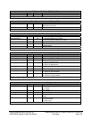
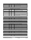
DMA2_Extend - RW – 8 bits - [IO_Reg: 4D6h]
Field Name Bits Default Description
DMA2_Extend 7:0 00h DMA2 extended write mode register
DMA2_Extend register
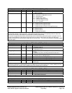
Pci_Intr_Index - RW – 8 bits - [IO_Reg: C00h]
Field Name Bits Default Description
Pci_Intr_Index 7:0 00h PCI interrupt index – selects which PCI interrupt to map
0h – INTA#
1h – INTB#
2h – INTC#
3h – INTD#
4h – Interrupt generated by ACPI
5h – Interrupt generated by Sm Bus
6h – Reserved
7h – Ac97 audio
8h – Ac97 modem
9h – INTE#
Ah – INTF#
Bh – INTG#
Ch – INTH#
Pci_Intr_Index register