


©2008 Advanced Micro Devices, Inc.
AC ’97 Controller Functional Descriptions
AMD SB600 Register Reference Manual Proprietary Page 204
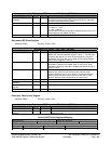
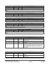
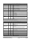
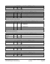
Interrupt - RW - 32 bits - [MEM_Reg: 00h]
Field Name Bits Default Description
in DMA Overflow 0 0b Input Channel overflow on the next AC'97 clock - out of FIFO space.
in DMA Status 1 0b Set to “1” after finishing an input audio DT data block (if
reg0x04[1]=1 and reg0x08[3]=0).
out DMA Underflow 2 0b Output Channel underflow on the next AC'97 clock – no data in
FIFO
out DMA Status 3 0b Set to "1" after finishing an output audio DT data block (if
reg0x04[1]=1 and reg0x08[3]=0).
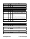
SPDIF Underflow 4 0b SPDIF is out of data
SPDIF Status 5 0b SPDIF status bit - set to "1" after finishing an SPDIF DT data block
(if reg0x04[5]=1 and reg0x08[5]=0).
Reserved 7:6 0b
Phy Data Incoming 8 0b Got OR’ed Physical register address and data from Codecs
Phy Addr Mismatch 9 0b There is mismatch between in Physical and out Physical address
values
Codec0 Not Ready 10 0b The Ac97_Phy registers in the master Ac97 codec are not ready for
normal operation
Codec1 Not Ready 11 0b The Ac97_Phy registers in the 1
st
slave Ac97 codec are not ready
for normal operation
Codec2 Not Ready 12 0b The Ac97_Phy registers in the 2
nd
slave Ac97 codec are not ready
for normal operation
New Frame Starts 13 0b This bit is set when new frame starts
Reserved 14 0b
Audio Gpio Interrupt 15 0b When the input audio GPIO interrupt is enabled, input bus slot 12 bit
0 is considered as audio GPIO data. When that is true, if slot 12 is
valid and bit 0 changes, this bit is set to indicate audio GPIO
interrupt.
Reserved 31:16 0000h
Interrupt Source Register: Each bit in this register expresses an error flag. "1" indicates the error. Driver can read
status or clear by writing “1”. Writing 0 to bit doesn't change its value.
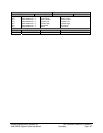
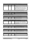
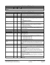
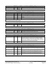
Interrupt Enable- RW - 32 bits - [MEM_Reg: 04h]
Field Name Bits Default Description
in DMA Overflow en. 0 0b Enable Input Channel overflow interrupt.
Audio Status Enable 1 0b 1- When an input or output audio DT data block is finished, status
will be updated in either DT memory or in reg0x00 (depending on
reg0x08[3]).
0 – Don’t update status
out DMA Underflow en 2 0b Enable Output channel 0 underflow interrupt.
Out DMA Underflow
Condition Select
3 0b 0—Underflow interrupt is asserted only when output DMA FIFO has
zero valid entry.
1—Underflow interrupt is asserted as long as output DMA FIFO
does not have enough valid entries for the coming frame
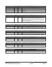
SPDIF Underflow en 4 0b Enable SPDIF underflow interrupt.
SPDIF Status enable 5 0b 1- When an SPDIF DT data block is finished, status will be updated
in either DT memory or in reg0x00 (depending on reg0x08[5]).
0 – Don’t update status
Reserved 7:6 00b
Phy in Interrupt en 8 0b Enable "Got Physical register data from Codec" interrupt
Phy_addr_mismatch_e
n
9 0b Enable Physical address in/out mismatch interrupt
Codec0 Not Ready En 10 0b Enable Codec0_not_ready interrupt
Codec1 Not Ready En 11 0b Enable Codec1_not_ready interrupt
Codec2 Not Ready En 12 0b Enable Codec2_not_ready interrupt
New Frame Start En 13 0b Enable new frame start interrupt
Set Bus Busy Audio 14 0b Audio is running (write only). Set/cleared by software.
Audio gpio interrupt en 15 0b Enable audio GPIO interrupt