©2008 Advanced Micro Devices, Inc.
SMBus Module and ACPI Block (Device 20, Function 0)
AMD SB600 Register Reference Manual Proprietary Page 172
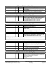
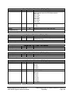
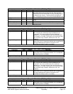
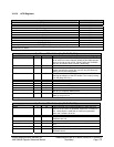
AutoArbDisWaitTime - RW - 8 bits - [PM_Reg: 9Fh]
Field Name Bits Default Description
AutoArbDisWaitTime 3:0 0h This defines the amount of time (in 2us increment) that SB will
hold ARB_DIS set after breaking from C3. This is to allow
sometime for CPU to resume from C3 before allowing any bus
mastering to the memory. This timer has an uncertainty of -
2us. This applies to K8 C1e or P4 LVL3 if AutoArbDisEn is set.
HPET_DisablePeriodic 4 0h Set to 1 to make Periodical capability bit appear to be 0.
HPET_Load 5 0h Set to 1 to make HPET timer load the new value in periodical
mode
ASFRemoteDelay 6 0h Set to 1 to delay the remote action(reset,power dwon..)
RstCstate/9E 7 0h Set to 1 to make state machine of C state reset by pcirst,
otherwise rsmrst
AutoArbDisWaitTime register
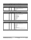
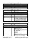
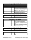
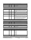
Programlo4RangeLo - RW – 8 bits - [PM_Reg: A0h]
Field Name Bits Default Description
ProgramIo4Mask 3:0 0h These four bits are used to mask the least 4 bits of the 16 bit
I/O. If bit [3] is set, then bit [3] of the I/O address is not
compared. If it is not set, then bit [3] of the monitored
address is 0. The same applies for the other three bits [2:0].
For example, if x15=80h, x14[7:4]=Ah, and x14[3:0]=3h, then
the monitored range is 80A4h : 80A0h (bit 0 and 1 are
masked)
ProgramIo4RangeLo 7:4 0h I/O range base address; these bits define the least significant
byte of the 16 bit I/O range base address that is programmed
to trigger SMI# when the address is accessed. Bit 7
corresponds to Addr[7] and bit 4 to Addr[4].
ProgramIo4RangeLo register
ProgramIo4RangeHi - RW – 8 bits - [PM_Reg: A1h]
Field Name Bits Default Description
ProgramIo4RangeHi 7:0 00h I/O range base address; these bits define the most significant
byte of the 16 bit I/O range base address. Bit 7 corresponds
to Addr[15] and bit 0 to Addr[8].
ProgramIo4RangeHi register
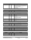
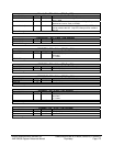
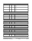
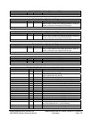
Programlo5RangeLo - RW – 8 bits - [PM_Reg: A2h]
Field Name Bits Default Description
ProgramIo5Mask 3:0 0h These four bits are used to mask the least 4 bits of the 16 bit
I/O. If bit [3] is set, then bit [3] of the I/O address is not
compared. If it is not set, then bit [3] of the monitored
address is 0. The same applies for the other three bits [2:0].
For example, if x15=80h, x14[7:4]=Ah, and x14[3:0]=3h, then
the monitored range is 80A4h : 80A0h (bit 0 and 1 are
masked)
ProgramIo5RangeLo 7:4 0h I/O range base address; these bits define the least significant
byte of the 16 bit I/O range base address that is programmed
to trigger SMI# when the address is accessed. Bit 7
corresponds to Addr[7] and bit 4 to Addr[4].
ProgramIo5RangeLo register
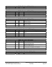
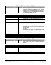
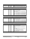
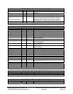
ProgramIo5RangeHi - RW – 8 bits - [PM_Reg: A3h]
Field Name Bits Default Description
ProgramIo5RangeHi 7:0 00h I/O range base address; these bits define the most significant
byte of the 16 bit I/O range base address. Bit 7 corresponds
to Addr[15] and bit 0 to Addr[8].


