


©2008 Advanced Micro Devices, Inc.
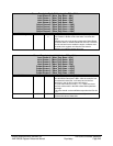
LPC ISA Bridge (Device 20, Function 3)
AMD SB600 Register Reference Manual Proprietary Page 254
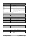
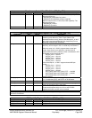
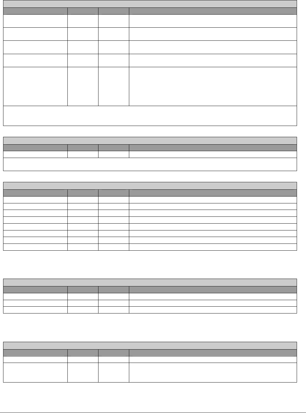
IO/Mem Port Decode Enable Register 5- RW - 8 bits - [PCI_Reg: 48h]
Field Name Bits Default Description
Rom Range 1 Port
Enable
3 0b Port enable for LPC ROM address range 1 (memory), see
register 68-6bh
Rom Range 2 Port
Enable
4 0b Port enable for LPC ROM address range 2 (memory), see
register 6c-6fh
Memory Range Port
Enable
5 0b Port enable for LPC memory target range, see register 60-63h
RTC IO Range Port
Enable
6 0b Port enable for RTC I/O range 70h~73h
Sync Timeout Counter
Enable
7 1b LPC sync timeout counter enabled when set to ‘1’ (default),
otherwise the counter is disabled. This counter is used to avoid
a deadlock condition if an LPC device drives sync forever.
Timeout count is programmed in register 49h. Write ‘0’ to this bit
if an LPC device is extremely slow & takes more than 255 LPC
clocks to complete a cycle.
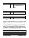
This register controls the decoding of Super IO configuration, alternate super-IO configuration, wide generic ports,
ROM1 & ROM2 ports, and memory port. Writing ‘1’ to a bit enables the corresponding IO/ROM/Memory range. Bit
7 controls enable/disable of LPC sync timeout counter.
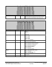
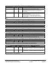
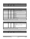
LPC Sync Timeout Count - RW - 8 bits - [PCI_Reg: 49h]
Field Name Bits Default Description
Sync Timeout Count 7:0 FFh Sync Timeout Count.
This register contains the value of LPC sync timeout count. This is the number of LPC clocks the state machine will
wait when LPC data = sync before aborting the cycle (when timeout counter is enabled; see register 48, bit 7).
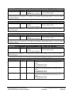
IO/Mem Port Decode Enable Register 6- RW - 8 bits - [PCI_Reg: 4Ah]
Field Name Bits Default Description
IO port enable 0 0 0b Port enable for IO port 400h-43Fh
IO port enable 1 1 0b Port enable for IO port 480h-4BFh
IO port enable 2 2 0b Port enable for IO port 500h-53Fh
IO port enable 3 3 0b Port enable for IO port 580h-5BFh
Mem port enable 4 0b Port enable for 4K byte memory range defined in reg0x4C
IO port enable 4 5 0b Port enable for IO port 80h
IO port enable 5 6 0b Port enable for IO port 4700h-470Bh
IO port enable 6 7 0b Port enable for IO port FD60h-FD6Fh
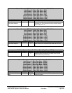
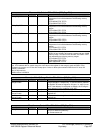
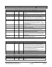
IO/Mem Port Decode Enable Register 7- RW - 8 bits - [PCI_Reg: 4Bh]
Field Name Bits Default Description
Wide_io1_enable 0 0b Wide IO port 1 (defined in register 66/67h) enable
Wide_io2_enable 1 0b Wide IO port 2 (defined in register 90/91h) enable
Reserved 7:2 00h
Memory Range Register - RW - 32 bits - [PCI_Reg: 4Ch]
Field Name Bits Default Description
Reserved 11:0 000h
Base Address 31:12 00000h This register defines a 4K byte memory range from {Base
Address, 000h} to {Base Address, fffh}. The range is enabled by
reg0x4A[4].