


©2008 Advanced Micro Devices, Inc.
SMBus Module and ACPI Block (Device 20, Function 0)
AMD SB600 Register Reference Manual Proprietary Page 163
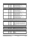
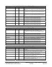
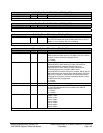
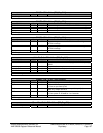
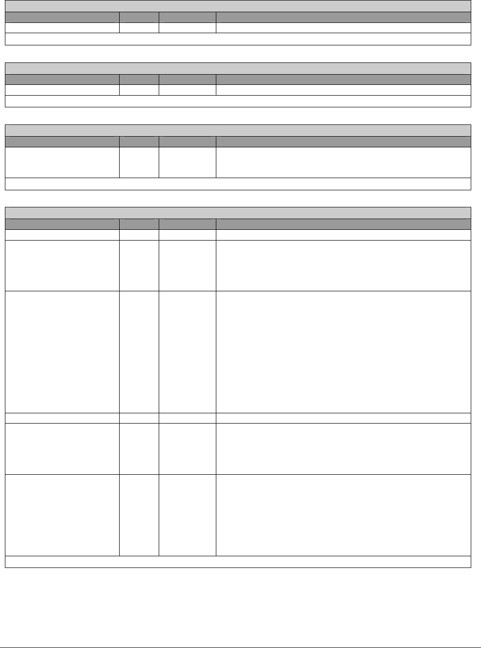
WatchDogTimerBase2 – RW – 8 bits – [PM_Reg:6Eh]
Field Name Bits Default Description
WatchDogTimerBase2 7:0 00h WatchDogTimer Base address [23:16]
WatchDogTimerBase2 register
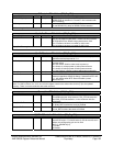
WatchDogTimerBase3 – RW – 8 bits – [PM_Reg:6Fh]
Field Name Bits Default Description
WatchDogTimerBase3 7:0 00h WatchDogTimer Base address [31:24]
WatchDogTimerBase3 register
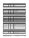
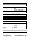
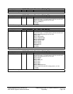
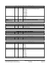
S_LdtStartTime – RW – 8 bits – [PM_Reg:70h]
Field Name Bits Default Description
S_LdtStartTime 7:0 00h This register defines the delay between SUS_STAT# assertion
and LDTSTP# assertion when the K8 system enters ACPI S
states, in 1us increment, with 1us uncertainty.
S_LdtStartTime register
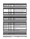
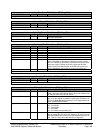
EnhanceOption – RW – 8 bits – [PM_Reg:71h]
Field Name Bits Default Description
Reserved 0 0b
P4C34PopUpEn 1 0b If enabled, for P4 system C3/4 can pop up to C2 for internal
DMA request and back down to C3/4 after A-link bus is idle for
number of clocks defined by PopUpEndTime.
1 = Enable
0 = Disable
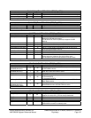
C2EnhanceEn 2 0b For both P4 and K8 system, in C2 state NB can toggle
SLP#/LDTSTP#. When entering C2 state, SB sends out
STPCLK# assertion message. NB takes control of
SLP#/LDTSTP#. When exiting C2 state, SB sends out
STPCLK# de-assertion message. NB de-assert
SLP#/LDTSTP# if needed. If this bit is enabled, SB will wait for
NB to send the same message back then de-assert STPCLK#
signal for P4 system or send another STPCLK# de-assertion
message for K8 system. If this bit is disabled, SB will not wait
for NB to send the message back.
1 = Enable
0 = Disable
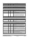
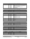
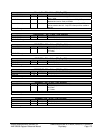
Reserved 3 0b
VidFidExtraDelayEn 4 0b If enabled, extra duration of LDTSTP# assertion as specified
by VidFidExtraDelaySelect will be added to the VID/FID
change sequence.
1 = Enable
0 = Disable
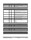
VidFidExtraDelaySelect 7:5 000b 3’b000: 0ns
3'b001: 140ns
3'b010: 210ns
3'b011: 280ns
3'b110: 350ns
3'b111: 420ns
3'b100: 490ns
3'b101: 560ns
EnhanceOption register