


©2008 Advanced Micro Devices, Inc.
HD Audio Controllers Registers
AMD SB600 Register Reference Manual Proprietary Page 240
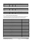
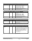
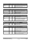
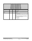
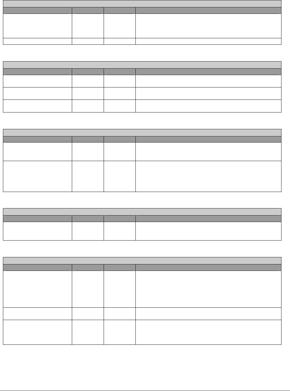
CORB Status – RW – 8 bits – [Mem_Reg: Base + 4Dh]
Field Name Bits Default Description
CORB Memory error
Indication
0 0b If this status bit is set, the controller has detected an error
in the pathway between the controller and memory. Writing
a “1” to this bit will clear the bit, but a CRST must be
performed before operation continues/
Reserved 7:2 00h Reserved. Software must use 0’s for write to these bits.
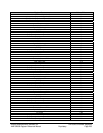
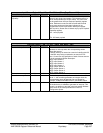
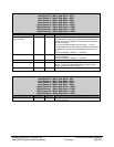
CORB Size – RW – 8 bits – [Mem_Reg: Base + 4Eh]
Field Name Bits Default Description
CORB Size 1:0 10b These bits have no functional impact to the hardware.
This HD Audio controller only supports 256 entries.
Reserved 3:2 0h Reserved. Software must do a read-modify-write to
preserve the value of these bits.
CORB Size Capability 7:4 0100b Hardwired to 0100b indicating this controller only supports
a CORB size of 256 entries.
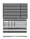
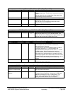
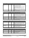
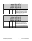
RIRB Lower Base Address – RW – 32 bits – [Mem_Reg: Base + 50h]
Field Name Bits Default Description
RIRB Lower Base
Address Unimplemented
Bits
6:0 00h Hardwired to 0. This forces 128-byte buffer alignment for
cache line fetch optimizations.
RIRB Lower Base
Address
31:7 0000000h Upper 25 bits of the 32 bits Lower Base Address of the
Response Input Ring Buffer, allowing the RIRB Base
Address to be assigned on any 2 KB boundary. This
register must not be written when the DMA engine is
running or the DMA transfer may be corrupted.
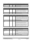
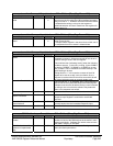
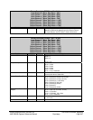
RIRB Upper Address – RW – 32 bits – [Mem_Reg: Base + 54h]
Field Name Bits Default Description
RIRB Upper Base
Address
31:0 00000000
h
Upper 32 bits address of the RIRB. This register must not
be written when the DMA engine is running or the DMA
transfer may be corrupted.
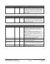
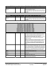
RIRB Write Pointer – RW – 16 bits – [Mem_Reg: Base + 58h]
Field Name Bits Default Description
RIRB Write Pointer 7:0 00h This field indicates the last valid RIRB entry written by the
DMA controller. Software reads this field to determine how
many responses it can read from the RIRB. The value read
indicates the RIRB Write Pointer offset in two dwords since
each RIRB entry is two dwords. This field may be read
while the DMA engine is running.
Reserved 14:8 00h Reserved. Software must do a read-modify-write to
preserve the value of these bits.
RIRB Write Pointer Reset 15 0b Software writes a “1” to this bit to reset the RIRB Write
Pointer to 0’s. The DMA engine must be stopped prior to
resetting the Write Pointer or else DMA transfer may be
corrupted. This bit will always be read as 0.