©2008 Advanced Micro Devices, Inc.
LPC ISA Bridge (Device 20, Function 3)
AMD SB600 Register Reference Manual Proprietary Page 250
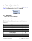
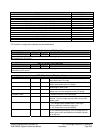
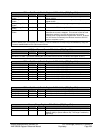
Register Name Offset Address
Rom Protect 1 54h
Rom Protect 2 58h
Rom Protect 3 5Ch
PCI Memory Start Address for LPC Target Cycles 60h
PCI Memory End Address for LPC Target Cycles 62h
PCI IO base Address for Wide Generic Port 64h
LPC ROM Address Range 1 (Start Address) 68h
LPC ROM Address Range 1 (End Address) 6Ah
LPC ROM Address Range 2 (Start Address) 6Ch
LPC ROM Address Range 2 (End Address) 6Eh
Firmware Hub Select 70h
Alternative Wide Io Range Enable 74h
Reserved 78h
TPM register 7Ch
MSI Capability register 80h
PCI function 3 configuration registers are described below.
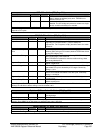
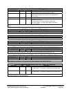
VID- R - 16 bits - [PCI_Reg: 00h]
Field Name Bits Default Description
Vendor ID 15:0 1002h Vendor ID
Vendor ID Register: This register holds a unique 16-bit value assigned to a vendor, and combined with the device
ID it identifies any PCI device.
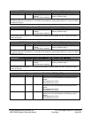
DID- R - 16 bits - [PCI_Reg: 02h]
Field Name Bits Default Description
Devide ID 15:0 438Dh Device ID
Device ID Register: This register holds a unique 16-bit value assigned to a device and together with the vendor ID,
it identifies any PCI device.
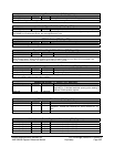
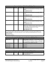
CMD- RW - 16 bits - [PCI_Reg: 04h]
Field Name Bits Default Description
IO Space 0 1b Hardcoded to 1 to enable IO access, since legacy IOs
reside behind the LPC bridge.
Memory Space 1 1b Hardcoded to 1 to enable Memory Access, since BIOS
ROM is located behind the LPC bridge.
Bus Master 2 1b Hardcoded to 1 to enable bus master, since LPC bridge
handles legacy DMA cycles.
Special Cycles 3 1b Hardcoded to 1 to enable Special Cycle recognition, since
special cycle must be recognized by the LPC bridge.
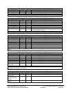
Memory Write and
Invalidate Enable
4 0b Hardcoded to 0 to indicate that Memory Write and
Invalidate command is not implemented.
VGA Palette Snoop 5 0b Hardcoded to 0 to indicate that VGA Palette Snoop is
disabled - The LPC bridge does not need to snoop VGA
palette cycles.
Parity Error Response 6 0b PERR# (Response) Detection Enable bit.
1 - LPC bridge asserts PERR# when it is the agent
receiving data AND it detects a parity error.
0 – LPC bridge does not assert PERR#.
Stepping Control 7 0b Hardcoded to 0 to indicate that LPC bridge does not use
perform address/data stepping - the LPC bridge does not
need to insert a wait state between the address and data
on the AD lines.


