©2008 Advanced Micro Devices, Inc.
OCHI USB 1.1 and EHCI USB 2.0 Controllers
AMD SB600 Register Reference Manual Proprietary Page 77
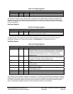
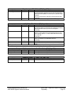
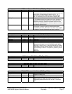
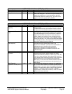
PME Data / Status – RW - 32 bits - [PCI_Reg : C4h]
Field Name Bits Default Description
B2_B3# 22 1b Read only.
The state of this bit determines the action that is to occur as a
direct result of programming the function to D3hot.. A “1”
indicates that when the bridge function is programmed to
D3
hot, its secondary bus’s PCI clock will be stopped (B2).
BPCC_En 23 0b Read only.
A “0” indicates that the bus power/clock control policies are
disabled. When the Bus Power/Clock Control mechanism is
disabled, the bridge’s PMCSR PowerState field cannot be
used by the system software to control the power or clock of
the bridge’s secondary bus.
Data 31:24 00h Read only.
This register is used to report the state dependent data
requested by the Data_Select field. The value of this register
is scaled by the value reported by the Data_Scale field.
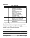
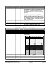
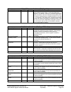
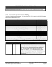
MSI Control – RW - 32 bits - [PCI_Reg : D0h]
Field Name Bits Default Description
MSI USB 7:0 05h MSI USB ID. Read only.
Next Item Pointer 15:8 E4h Pointer to next capability structure
MSI Control Out 16 0b Set to 1 to disable IRQ. Use MSI instead.
Reserved 19:17 0h Reserved
MSI Control 22:20 0h MSI control field
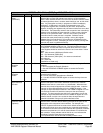
64-bit Address Capable 23 0b If EHCI is in 64 bit address mode as specified by 64-bit
Addressing Capability bit in HCCPARAMS register [MEM
Reg: 08h] , this bit is set to 1 indicating that EHCI is capable
of generating a 64-bit message address. Otherwise it is set
to 0 indicating the EHCI is not capable of generating a 64-bit
address.
Read only
Reserved 31:24 00h Reserved
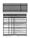
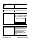
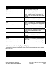
MSI Address – RW - 32 bits - [PCI_Reg : D4h]
Field Name Bits Default Description
MSI Address 31:0 0h System-specified message address.
MSI Data – RW - 16 bits - [PCI_Reg : D8h]
Field Name Bits Default Description
MSI Data 15:0 0h System-specified message
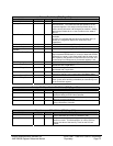
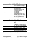
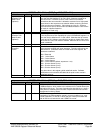
DBUG_PRT Control – R - 32 bits - [PCI_Reg : E4h]
Field Name Bits Default Description
CAP_ID 7:0 0Ah The value of 0Ah in this field identifies that the function
supports a Debug Port.
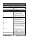
Next Item Pointer 15:8 00h Pointer to next capability structure
Offset 28:16 0E0h This 12 bit field indicates the byte offset (up to 4K) within the
BAR indicated by BAR#. This offset is required to be
DWORD aligned and therefore bits 16 and 17 are always
zero.


