


©2008 Advanced Micro Devices, Inc.
SATA Registers (Device 18, Function 0)
AMD SB600 Register Reference Manual Proprietary Page 24
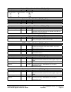
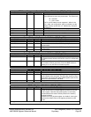
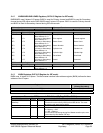
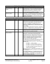
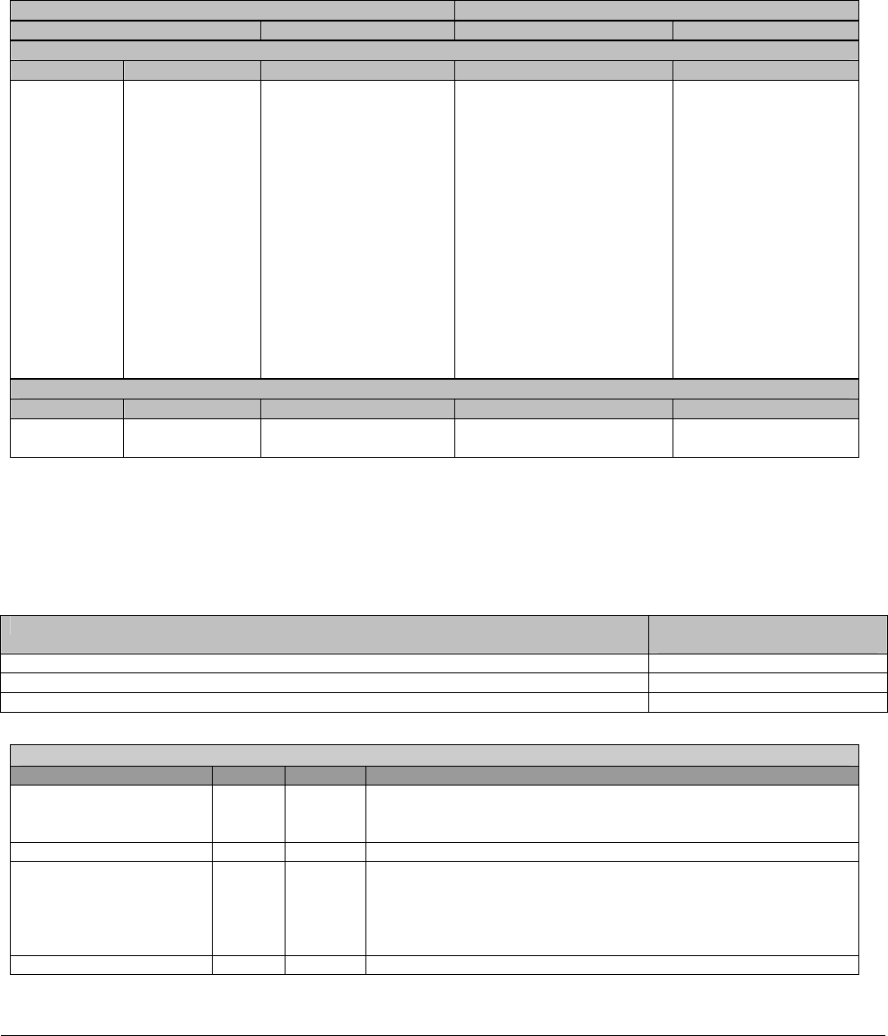
2.1.2 BAR0/BAR2/BAR1/BAR3 Registers (SATA I/O Register for IDE mode)
BAR0/BAR2 uses 8 bytes of I/O space. BAR0 is used for Primary channel and BAR2 is used for Secondary
channel during IDE native mode. BAR1/BAR3 uses 2 bytes of I/O space. BAR1 is used for Primary channel
and BAR3 is used for Secondary channel during IDE native mode.
Address (hex) Name and Function
Compatibility Mode Native Mode (Offset) Read Function Write Function
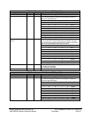
IDE Command Block Registers
Primary Secondary BAR0/BAR2
1F0 170 (Primary or Secondary)
Base Address 0 + 0
Data (16 bit) Data (16 bit)
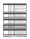
1F1 171 (Primary or Secondary)
Base Address 0 + 1
Error register Features register
1F2 172 (Primary or Secondary)
Base Address 0 + 2
Sector Count Sector Count
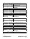
1F3 173 (Primary or Secondary)
Base Address + 3
Sector Number Sector Number
1F4 174 (Primary or Secondary)
Base Address + 4
Cylinder Low Cylinder Low
1F5 175 (Primary or Secondary)
Base Address + 5
Cylinder High Cylinder High
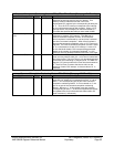
1F6 176 (Primary or Secondary)
Base Address + 6
Drive/Head Drive/Head
1F7 177 (Primary or Secondary)
Base Address + 7
Status Command
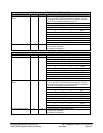
IDE Control Block Registers
Primary Secondary BAR1/BAR3
3F6 376 (Primary or Secondary)
Base Address + 2
Alternate Status Device Control
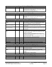
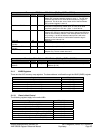
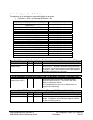
2.1.3 BAR4 Registers (SATA I/O Register for IDE mode)
BAR4 uses 16 bytes of I/O space. The Bus-master interface base address register (BAR4) defines the base
address of the IO spare.
Register Name Offset Address
[Primary/Secondary]
Bus-master IDE Command 00h/08h
Bus-master IDE Status 02h/0Ah
Descriptor Table Pointer 04h/0Ch
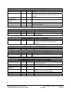
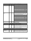
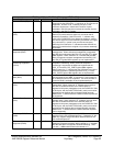
Bus-master IDE Command - RW- 8 bits - [IO_Reg: BAR4 + 00/08h]
Field Name Bits Default Description
Bus Master IDE
Start/Stop
0 0b Bus Master IDE Start (1)/Stop (0).
This bit will not be reset by interrupt from IDE device. This must
be reset by soft ware (device driver).
Reserved 2:1 Reserved.
Bus Master Read/Write 3 0b Bus Master IDE r/w (direction) control
0 = Memory -> IDE
1 = IDE -> Memory
This bit should not change during Bus Master transfer cycle, even
if terminated by Bus Master IDE stop.
Reserved 7:4 Reserved.