©2008 Advanced Micro Devices, Inc.
AC ’97 Controller Functional Descriptions
AMD SB600 Register Reference Manual Proprietary Page 205
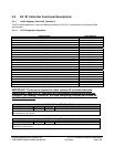
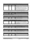
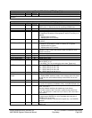
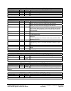
Interrupt Enable- RW - 32 bits - [MEM_Reg: 04h]
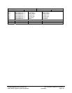
Field Name Bits Default Description
Reserved 31:16 0000h
Interrupt Enable Register: If a bit in this register is set to “1”, the corresponding interrupt is enabled. Default—all
disabled.
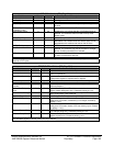
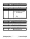
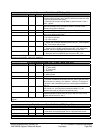
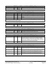
Audio Command- RW - 32 bits - [MEM_Reg: 08h]
Field Name Bits Default Description
Power down 0 0b When this bit is set, the INTA# will be only set when any of the
SDATA_IN is '1'. Should be used for catching of PME# event.
Audio receive enable 1 0b Enable receiving of audio data from AC-link.
Audio send out enable 2 0b Enables sending of audio data to AC97 link.
Audio Status To Mem 3 0b When reg0x04[1] is enabled, after finishing an input or output audio
DT data block, the status will be updated in either DT memory or in
reg0x00.
0 – Update status to register.
1 – Update status to DT memory.
SPDIF send out en 4 0b Enable SPDIF to send out data. Also it enables Underflow interrupt
for SPDIF.
SPDIF Status To Mem 5 0b When reg0x04[5] is enabled, after finishing an SPDIF DT data block,
the status will be updated in either DT memory or in reg0x00.
0 – Update status to register.
1 – Update status to DT memory.
Modem_slots_alloc_1 6 0b Mirror bit of modem memory mapped register0x08[6]. This is only
available in ASIC revision A32 or later. Refer to that bit for more
detailed information.
Reserved 7 0b
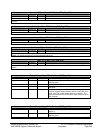
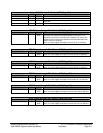
in DMA enable 8 0b Enable input DMA
out DMA enable 9 0b Enable output DMA
SPDIF DMA enable 10 0b Enable SPDIF DMA
SPDIF out Stopped 11 0b 1 - the SPDIF_OUT is set to the 0 because SPDIF FIFO run out of
data or SPDIF_en =0
0 - the SPDIF_OUT is processing the active data. [Read-only]
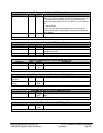
SPDIF concurrency 14:12 0h 000 – no SPDIF concurrency, SPDIF data go to SPDIF bus.
001 – SPDIF data go to slot 3 & 4
010 – SPDIF data go to slot 7 & 8
011 – SPDIF data go to slot 6 & 9
100 – SPDIF data go to slot 10 & 11
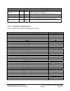
Reserved 15 0b
SPDIF interleave
enable
16 0b 0 – Disable SPDIF interleave mode
1 – Enable SPDIF interleave mode. In this mode a 32-bit PCI dword
will split into two 16-bit words and be put onto SPDIF bus as two
frames.
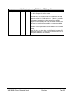
Reserved 19:17 0h
Audio present 20 0b 1 - Audio is present
0 - Audio is not present (for Modem driver), set by BIOS [Read-only]
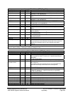
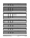
Interleave in 21 0b 1 - Enable Interleave format for the input slot 3 and 4 data, 31:16 -
slot 4, 15:0- slot 3.
Also this disables catching and transferring of slot 6 data.
0 - Enable transfer of slot 3,4 and 6 in regular format, where bits
31:12 - data and bits 11:8 are slot id (11 is slot 3, 100 is slot 4 and
110 is slot 6)
Interleave out 22 0b 1 - Enable transferring from memory the data in interleave format -
the upper part of DWORD [31:16] is right data and lower part of
DWORD [15:0] is left data.
0 - Data from memory is transferred in regular way - one DWORD ,
one data.
Loop back enable 23 0b Enable loop-back mode. The SDATA_OUT connected directly to the
SDATA_IN


