


©2008 Advanced Micro Devices, Inc.
IDE Controller (Device 20, Function 1)
AMD SB600 Register Reference Manual Proprietary Page 196
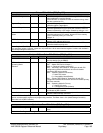
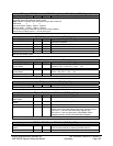
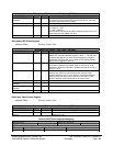
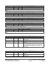
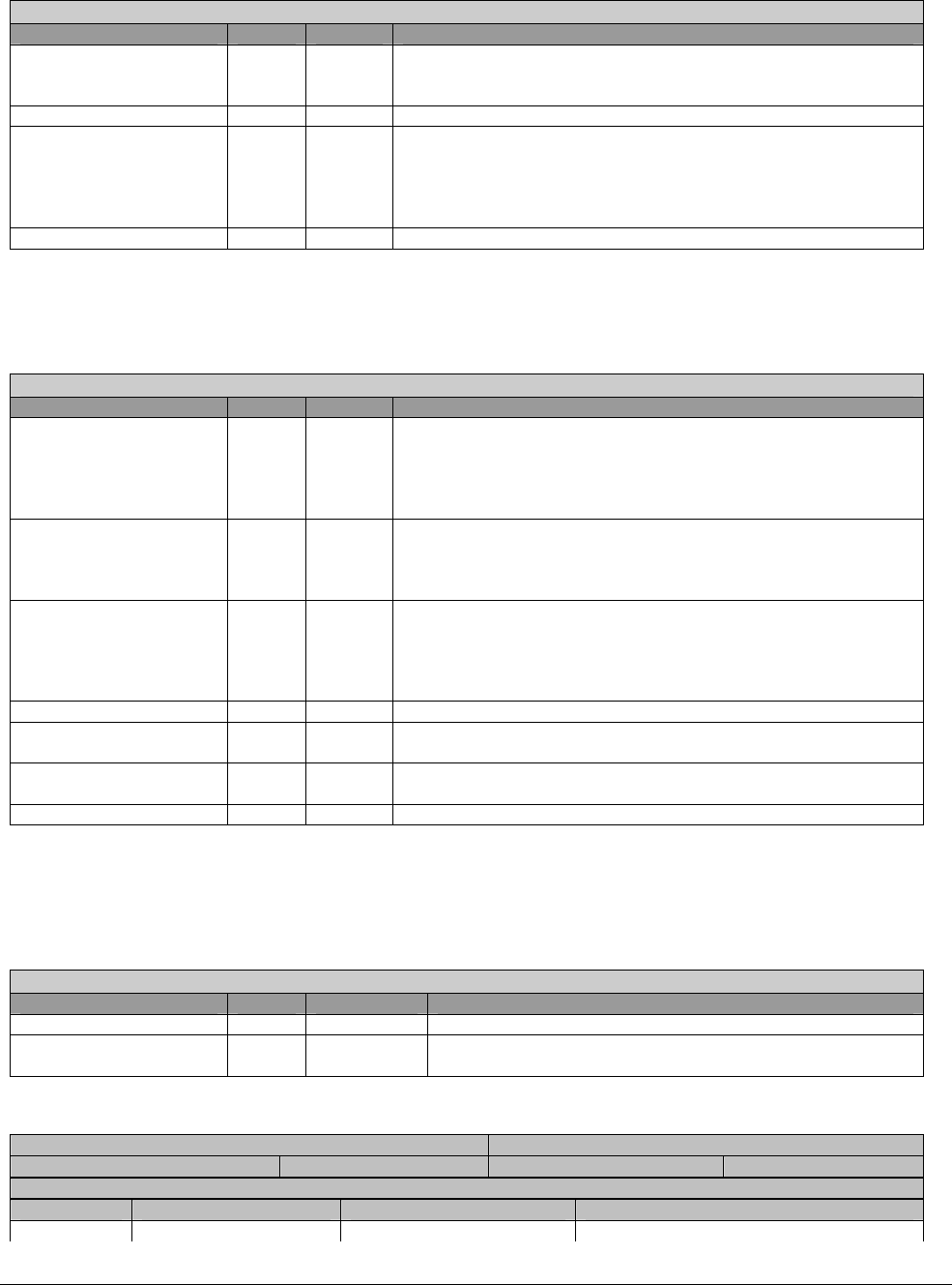
Bus-master IDE Command - RW- 8 bits - [IDE:00h]
Field Name Bits Default Description
Bus Master IDE
Start/Stop
0 0b Bus Master IDE Start (1)/Stop (0).
This bit will not be reset by interrupt from IDE device. This must
be reset by soft ware (device driver).
Reserved 2:1 0h Reserved. Wired 0’s.
Bus Master Read/Write 3 0b Bus Master IDE r/w (direction) control
0 = Memory -> IDE
1 = IDE -> Memory
This bit should not change during Bus Master transfer cycle, even
if terminated by Bus Master IDE stop.
Reserved 7:4 0h Reserved. These bits are always read as 0’s.
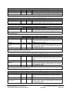
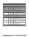
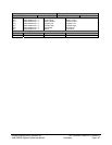
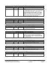
Bus-master IDE Status Register
Address Offset: Primary – Base + 02h
Bus-master IDE Status - RW- 8 bits - [IDE:02h]
Field Name Bits Default Description
Bus Master Active 0 0b Bus Master IDE active. This bit is set to 1 when bit 0 in the Bus
Master IDE command address register is set to 1. The IDE host
controller sets this bit to 0 when the last transfer for a region is
performed. This bit is also set to 0 when bit 0 of the Bus Master
IDE command register is set to 0.
Bus Master DMA Error 1 0b IDE DMA error. This bit is set when the IDE host controller
encounters a target abort, master abort, or Parity error while
transferring data on the PCI bus. Software sets this bit to a 0, by
writing a 1 to it.
IDE Interrupt 2 0b IDE Interrupt. Indicates when an IDE device has asserted its
interrupt line. IRQ14 is used for the primary channel. If the
interrupt status bit is set to 0, by writing a 1 to this bit while the
interrupt line is still at the active level, this bit remains 0 until
another assertion edge is detected on the interrupt line.
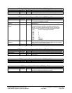
Reserved 4:3 0h Reserved. Always read as 0’s.
Master Device DMA
Capable
5 0b Device 0 (Master) DMA capable.
Slave Device DMA
Capable
6 0b Device 1 (Slave) DMA capable.
Simplex Only 7 0b Simplex only. This bit is hard-wired as 0.
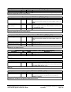
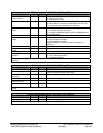
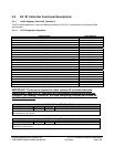
Descriptor Table Pointer Register
Address Offset: Primary – Base + 04h
Bus-master IDE Command - RW- 32 bits - [IDE:04h]
Field Name Bits Default Description
Reserved 1:0 0h Reserved. Always read as 0’s.
Descriptor Table Base
Address
31:2 0000_0000h Base Address of Descriptor Table. These bits correspond to
Address [31-02].
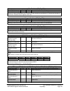
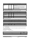
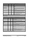
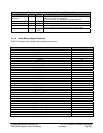
Table 2-8 IDE Device Registers Mapping
Address (hex) Name and Function
Compatibility Mode Native Mode (Offset) Read Function Write Function
IDE Command Block Registers
Primary
1F0 Base Address 0 + 0 Data (16 bit) Data (16 bit)