©2008 Advanced Micro Devices, Inc.
OCHI USB 1.1 and EHCI USB 2.0 Controllers
AMD SB600 Register Reference Manual Proprietary Page 70
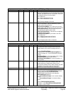
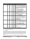
HceControl Register
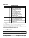
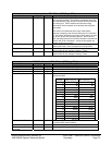
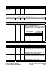
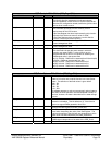
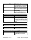
Table 2-7 HceControl Register
HceControl - 32 bits
Field Name Bits Reset Description
EmulationEnable 0 0b When set to 1, the HC is enabled for legacy emulation.
The HC decodes accesses to I/O registers 60h and 64h and
generates IRQ1 and/or IRQ12 when appropriate.
Additionally, the HC generate s an emulation interrupt at
appropriate times to invoke the emulation software.
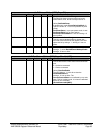
EmulationInterrupt 1 - This bit is a static decode of the emulation interrupt
condition. [Read-only]
CharacterPending 2 0b When set, an emulation interrupt is generated when the
OutputFull bit of the HceStatus register is set to 0.
IRQEn 3 0b When set, the HC generates IRQ1 or IRQ12 as long as the
OutputFull bit in HceStatus is set to 1. If the
AuxOutputFull bit of HceStatus is 0, then IRQ1 is
generated; if it is 1, then an IRQ12 is generated.
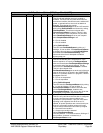
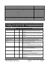
ExternalIRQEn 4 0b When set to 1, IRQ1 and IRQ12 from the keyboard
controller causes an emulation interrupt. The function
controlled by this bit is independent of the setting of the
EmulationEnable bit in this register.
GateA20Sequence 5 0b Set by HC when a data value of D1h is written to I/O port
64h. Cleared by HC on write to I/O port 64h of any value
other than D1h.
IRQ1Active 6 0b Indicates that a positive transition on IRQ1 from keyboard
controller has occurred. SW may write a 1 to this bit to
clear it (set it to 0). SW write of a 0 to this bit has no effect.
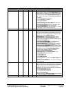
IRQ12Active 7 0b Indicates that a positive transition on IRQ12 from keyboard
controller has occurred. SW may write a 1 to this bit to
clear it (set it to 0). SW write of a 0 to this bit has no effect.
A20State 8 0b Indicates current state of Gate A20 on keyboard controller.
Used to compare against value written to 60h when
GateA20Sequence is active.
Reserved 31:9 - Must read as 0s.
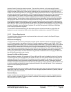
2.2.3 EHCI Registers (Device 19, Function 5)
The Enhanced USB Host Controller contains two sets of software accessible hardware registers—Memory-
mapped Host Controller Registers and optional PCI configuration registers (PCI_Reg).
Mapping into non-cacheable memory, Memory-mapped USB Host Controller Registers consists of a set of
read-only Capability registers (MEM_Reg) , a set of read/write operational registers(EOR_Reg) and a set of
read/write Debug Port registers (DBUG_Reg). Implemented as memory-mapped I/O space, the operational
registers are 32 bits in length and should be read and written as Dwords.
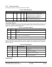
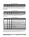
2.2.3.1 PCI Configuration Registers
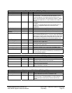
Registers Name Offset Address
Device / Vendor ID 00h
Command 04h
Status 06h
Revision ID / Class Code 08h
Miscellaneous 0Ch


