


©2008 Advanced Micro Devices, Inc.
OCHI USB 1.1 and EHCI USB 2.0 Controllers
AMD SB600 Register Reference Manual Proprietary Page 48
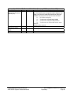
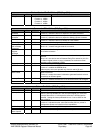
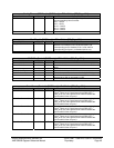
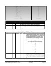
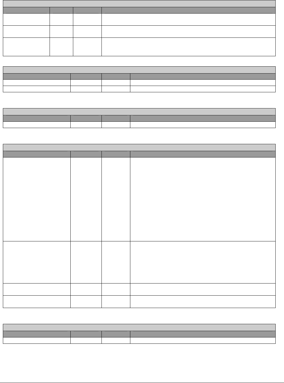
Bar_OHCI – RW - 32 bits - [PCI_Reg : 10h]
Field Name Bits Default Description
PM 3 0b Prefetch memory. A constant value of ‘0’ indicates that there is no
support for “prefetchable memory”. Read Only.
11:4 00h Represents a maximum of 4-KB addressing space for the OpenHCi’s
operational registers. Read Only.
BAR 31:12 000h Base Address. Specifies the upper 20 bits of the 32-bit starting base
address. This represent a maximum of 4-KB addressing space for the
OpenHCI’s operational registers.
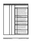
Subsystem Vendor ID / Subsystem ID – RW - 32 bits - [PCI_Reg : 2Ch]
Field Name Bits Default Description
Subsystem Vendor ID 15:0 0000h Can only be written once by software.
Subsystem ID 31:16 0000h Can only be written once by software.
Capability Pointer – R - 8 bits - [PCI_Reg : 34h]
Field Name Bits Default Description
Capability Pointer 7:0 D0h Address of the 1
st
element of capability link.
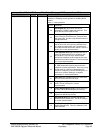
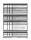
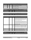
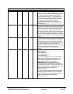
Interrupt Line – RW – 32 bits - [PCI_Reg : 3Ch]
Field Name Bits Default Description
Interrupt Line 7:0 00h The Interrupt Line register is an eight-bit register used to
communicate interrupt line routing information. The register
is read/write and must be implemented by any device (or
device function) that uses an interrupt pin. POST software
will write the routing information into this register as it
initializes and configures the system.
The value in this register tells which input of the system
interrupt controller(s) the device's interrupt pin is connected
to. The device itself does not use this value; rather it is used
by device drivers and operating systems. Device drivers
and operating systems can use this information to determine
priority and vector information. Values in this register are
system architecture specific.
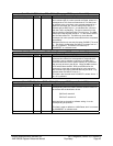
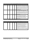
Interrupt Pin 15:8
01h
02h
03h
02h
03h
Read Only by default.
OHCI0: Hard-wired to 01h, corresponding to using INTA#.
OHCI1: Hard-wired to 02h, corresponding to using INTB#.
OHCI2: Hard-wired to 03h, corresponding to using INTC#.
OHCI3: Hard-wired to 02h, corresponding to using INTB#.
OHCI4: Hard-wired to 03h, corresponding to using INTC#.
MIN_GNT 23:16 00h Read Only. Hardwired to 00h to indicate no major
requirements for the settings of Latency Timers.
MAX_LAT 31:24 00h Read Only. Hardwired to 00h to indicate no major
requirements for the settings of the Latency Timers.
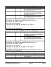
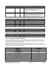
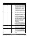
Config Timers / MSI Disable (OHCI0 only) – RW - 16 bits - [PCI_Reg : 40h]
Field Name Bits Default Description
TRDY Timer 7:0 80h Target Ready timer to timeout non-responding target.