


©2008 Advanced Micro Devices, Inc.
LPC ISA Bridge (Device 20, Function 3)
AMD SB600 Register Reference Manual Proprietary Page 256
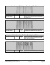
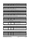
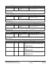
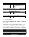
LPC ROM Address Range 1 (Start Address) - RW - 16 bits - [PCI_Reg: 68h]
Field Name Bits Default Description
Rom Start Address 1 15:0 0eh (if iLpc_Rom strap is
enabled),
00h (if the strap is disabled)
16-bit starting address of the LPC ROM
(memory) address range 1.
This register contains upper 16-bits of the starting address of the LPC ROM address range 1. The lower 16-bits of
the starting address are considered 0’s. This range can be enabled by setting register 48h, bit 3 or when LPC ROM
is chosen by strap pin.
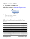
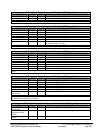
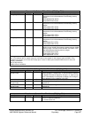
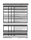
LPC ROM Address Range 1 (End Address) - RW - 16 bits - [PCI_Reg: 6Ah]
Field Name Bits Default Description
Rom End Address 1 15:0 0fh (if iLpc_Rom strap is
enabled),
00h (if the strap is disabled)
16-bit END address of the LPC ROM
(memory) address range 1.
This register contains upper 16-bits of the ending address of the LPC ROM address range 1. The lower 16-bits of
the end address are considered 1’s. This range can be enabled by setting register 48h, bit 3 or when LPC ROM is
chosen by strap pin.
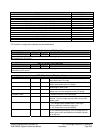
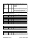
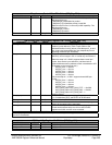
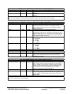
LPC ROM Address Range 2 (Start Address)- RW - 16 bits - [PCI_Reg: 6Ch]
Field Name Bits Default Description
Rom Start Address 2 15:0 FFFEh (if iLpc_Rom strap is
enabled),
00h (if the strap is disabled)
16-bit starting address of the LPC ROM
(memory) address range 2.
This register contains upper 16-bits of the starting address of the LPC ROM address range 2. The lower 16-bits of
the starting address are considered 0’s. This range can be enabled by setting register 48h, bit 4 or when LPC ROM
is chosen by strap pin.
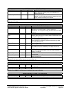
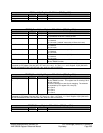
LPC ROM Address Range 2 (End Address) - RW - 16 bits - [PCI_Reg: 6Eh]
Field Name Bits Default Description
Rom End Address 2 15:0 FFFFh (if iLpc_Rom strap is
enabled),
00h (if the strap is disabled)
16-bit END address of the LPC ROM
(memory) address range 2.
This register contains upper 16-bits of the ending address of the LPC ROM address range 2. The lower 16-bits of
the end address are considered 1’s. This range can be enabled by setting register 48h, bit 4 or when LPC ROM is
chosen by strap pin.
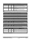
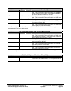
Firmware Hub Select – RW* - 32 bits - [PCI_Reg: 70h]
Field Name Bits Default Description
FWH_C0_IDSEL 3:0 7h IDSEL for two 512 KB FWH memory ranges. The IDSEL
programmed in this field addresses the following memory
ranges:
FFC0 0000h-FFC7 FFFFh
FF80 0000h-FF87 FFFFh
FWH_C8_IDSEL 7:4 6h IDSEL for two 512 KB FWH memory ranges. The IDSEL
programmed in this field addresses the following memory
ranges:
FFC8 0000h-FFCF FFFFh
FF88 0000h-FF8F FFFFh
FWH_D0_IDSEL 11:8 5h IDSEL for two 512 KB FWH memory ranges. The IDSEL
programmed in this field addresses the following memory
ranges:
FFD0 0000h-FFD7 FFFFh
FF90 0000h-FF97 FFFFh