


©2008 Advanced Micro Devices, Inc.
SMBus Module and ACPI Block (Device 20, Function 0)
AMD SB600 Register Reference Manual Proprietary Page 146
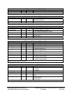
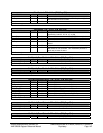
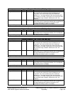
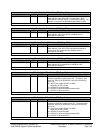
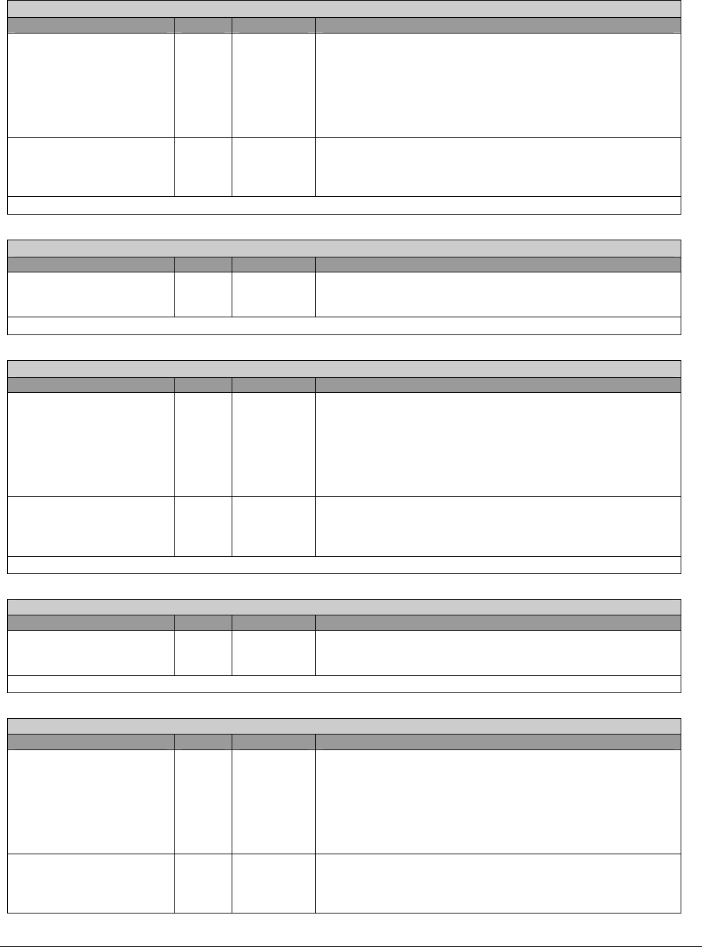
Programlo0RangeLo - RW – 8 bits - [PM_Reg: 14h]
Field Name Bits Default Description
ProgramIo0Mask 3:0 0h These four bits are used to mask the least 4 bits of the 16 bit
I/O. If bit [3] is set, then bit [3] of the I/O address is not
compared. If it is not set, then bit [3] of the monitored
address is 0. The same applies for the other three bits [2:0].
For example, if x15=80h, x14[7:4]=Ah, and x14[3:0]=3h, then
the monitored range is 80A4h : 80A0h (bit 0 and 1 are
masked)
ProgramIo0RangeLo 7:4 0h I/O range base address; these bits define the least significant
byte of the 16 bit I/O range base address that is programmed
to trigger SMI# when the address is accessed. Bit 7
corresponds to Addr[7] and bit 4 to Addr[4].
ProgramIo0RangeLo register.
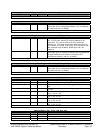
ProgramIo0RangeHi - RW – 8 bits - [PM_Reg: 15h]
Field Name Bits Default Description
ProgramIo0RangeHi 7:0 00h I/O range base address; these bits define the most significant
byte of the 16 bit I/O range base address. Bit 7 corresponds
to Addr[15] and bit 0 to Addr[8].
ProgramIo0RangeHi register.
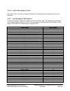
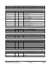
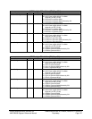
ProgramIo1RangeLo - RW – 8 bits - [PM_Reg: 16h]
Field Name Bits Default Description
ProgramIo1Mask 3:0 0h These four bits are used to mask the least 4 bits of the 16 bit
I/O. If bit [3] is set, then bit [3] of the I/O address is not
compared. If it is not set, then bit [3] of the monitored
address is 0. The same applies to the other three bits [2:0].
For example, if x15=80h, x14[7:4]=Ah, and x14[3:0]=3h, then
the monitored range is 80A4h : 80A0h (bit 0 and 1 are
masked)
ProgramI01RangeLo 7:4 0h I/O range base address; these bits define the least significant
byte of the 16 bit I/O range base address that is programmed
to trigger SMI# when the address is accessed. Bit 7
corresponds to Addr[7] and bit 4 to Addr[4].
ProgramIo1RangeLo register.
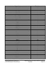
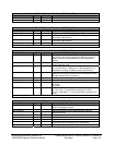
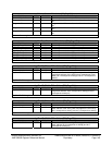
ProgramIo1RangeHi - RW – 8 bits - [PM_Reg: 17h]
Field Name Bits Default Description
ProgramIo1RangeHi 7:0 00h I/O range base address; these bits define the most significant
byte of the 16 bit I/O range base address. Bit 7 corresponds
to Addr[15] and bit 0 to Addr[8].
ProgramIO1RangeHi register.
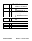
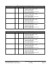
ProgramIo2RangeLo - RW – 8 bits - [PM_Reg: 18h]
Field Name Bits Default Description
ProgramIo2Mask 3:0 0h These four bits are used to mask the least 4 bits of the 16 bit
I/O. If bit [3] is set, then bit [3] of the I/O address is not
compared. If it is not set, then bit [3] of the monitored
address is 0. The same applies for the other three bits.
For example, if x15=80h, x14[7:4]=Ah, and x14[3:0]=3h, then
the monitored range is 80A4h : 80A0h (bit 0 and 1 are
masked)
ProgramIo2RangeLo 7:4 0h I/O range base address; these bits define the least significant
byte of the 16 bit I/O range base address that is programmed
to trigger SMI# when the address is accessed. Bit 7
corresponds to Addr[7] and bit 4 to Addr[4].