©2008 Advanced Micro Devices, Inc.
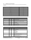
IDE Controller (Device 20, Function 1)
AMD SB600 Register Reference Manual Proprietary Page 190
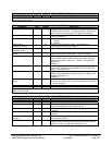
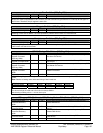
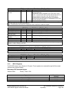
Base Address 2 - RW - 32 bits - [PCI_Reg:18h]
Field Name Bits Default Description
Reserved 31:16 0000h Reserved. Always read as 0’s.
Base Address 2 Register (Secondary CS0): This register identifies the base address of a contiguous IO space of
command register block for the primary channel.
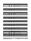
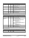
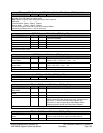
Base Address 3 - RW - 32 bits - [PCI_Reg:1Ch]
Field Name Bits Default Description
Resource Type Indicator 0 1b RTE (Resource Type Indicator). This bit is wired to 1 to
indicate that the base address field in this register maps to I/O
space.
Reserved 1 0b Reserved. Always read as 0’s.
Secondary IDE CS1
Base Address
15:2 0000h
Base Address for Secondary IDE Bus CS1. This
register is
used for native mode only. Base Address 3 is not used
in compatibility mode.
Reserved 31:16 0000h Reserved. Always read as 0’s.
Base Address 3 Register (Secondary CS1): This register identifies the base address of a contiguous IO space of
command register block for the primary channel.
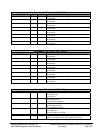
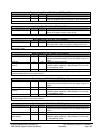
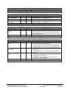
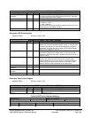
Bus Master Interface Base Address - RW - 32 bits - [PCI_Reg:20h]
Field Name Bits Default Description
Resource Type Indicator 0 1b RTE (Resource Type Indicator). This bit is wired to 1 to
indicate that the base address field in this register maps to I/O
space.
Reserved 3:1 0h Reserved. Always read as 0’s.
Bus Master Interface
Register Base Address
15:4 000h Base Address for Bus Master interface registers and
correspond to AD[15:4].
Reserved 31:16 0000h Reserved. Always read as 0’s.
Bus Master Interface Base Address Register: This register selects the base address of a 16-byte I/O space
interface for bus-master functions.
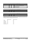
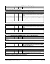
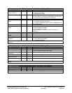
Subsystem ID and Subsystem Vendor ID – RW - 32 bits - [PCI_Reg:2Ch]
Field Name Bits Default Description
Subsystem Vendor ID 15:0 0000h Subsystem Vendor ID
Subsystem ID 31:16 0000h Subsystem ID
Subsystem ID and Subsystem Vendor ID: This subsystem ID and subsystem Vendor ID register is write once and
read only.
MSI Capabilities Pointer - R - 8 bits - [PCI_Reg:34h]
Field Name Bits Default Description
Capabilities Pointer 7:0 00h The first pointer of Capability block
Note: the capabilities pointer (0x70) can be enabled by setting
PCI config offset 0x62 bit 13 to 1
MSI Capabilities Pointer Register: This register will show the PCI configuration register starting address and it is
read only.
Interrupt Line - RW - 8 bits - [PCI_Reg:3Ch]
Field Name Bits Default Description
Interrupt Line 7:0 00h Identifies which input on the interrupt controller the function’s
PCI interrupt request pin (as specified in its Interrupt Pin
register) is routed to
Interrupt Line Register: This register identifies which of the system interrupt controllers the device interrupt pin is
connected to. The value of this register is used by device drivers.


