


Intel
®
IXP42X Product Line of Network Processors and IXC1100 Control Plane Processor
September 2006 DM
Order Number: 252480-006US 289
SDRAM Controller—Intel
®
IXP42X product line and IXC1100 control plane processors
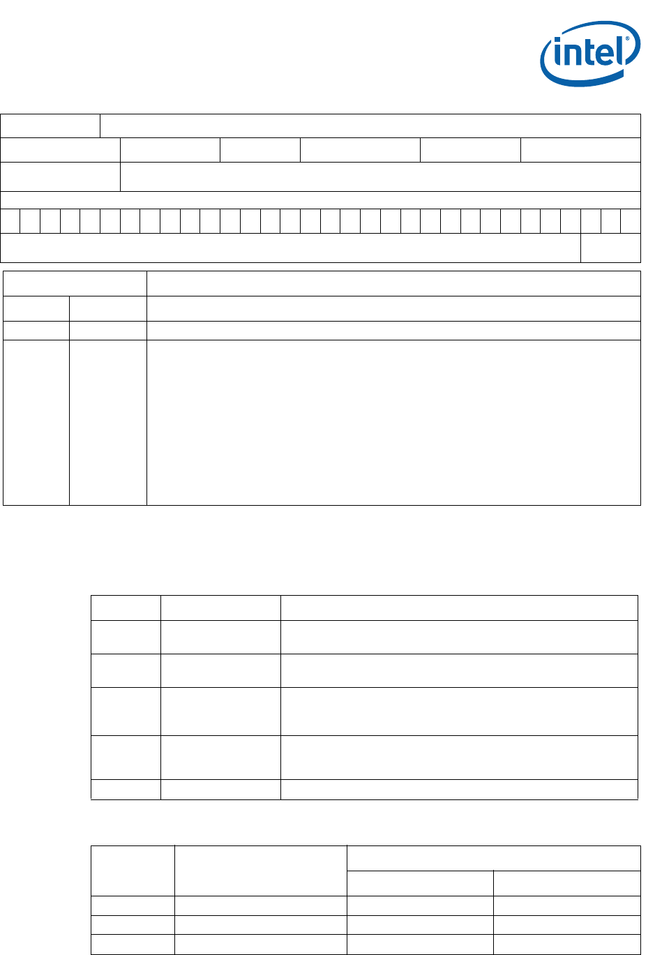
A “set mode register” command would write the following to the SDRAM. This is a
standard definition of a mode register from an SDRAM and not a register within the
SDRAM controller:
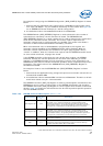
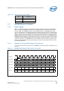
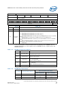
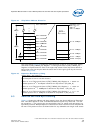
Register Name: SDR_IR
Hex Offset Address: 0xCC000008 Reset Hex Value: 0x00000000
Register Description:
Instruction register, holds commands that determine operation mode of the SDRAM controller and mode
register for SDRAMs.
Access: Read/Write
31 16 15 3 2 0
(Reserved)
Instruction
(command)
Register
SDR_IR
Bits Name Description
31:3 (Reserved)
2:0
Instruction
Register
Commands to be sent out to the SDRAM.
000 - Mode-Register-Set Command where CAS# Latency 2.
001 - Mode-Register-Set Command where CAS# Latency 3.
010 - Precharge-All Command: The MCU issues one precharge-all command to the SDRAM
devices.
011 - NOP Command: The MCU issues one NOP command to the SDRAM devices.
100 - Auto-Refresh Command: The MCU issues one auto-refresh command to the SDRAM
devices.
101 - Burst Terminate Command: The MCU issues one Burst Terminate command to the
SDRAM devices. This is intended to be used after reset only.
11x - (Reserved)
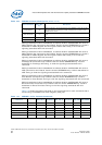
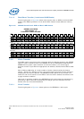
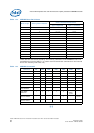
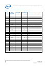
Table 114. SDRAM Configuration Options
[15:11] Don’t Care Don’t Care
10 Write Burst Mode
0 = Programmed burst length
1 = Single-location access
9:7 Operating Mode
00 = Standard operation
All other values reserved.
6:4 CAS Latency
010 = For two cycles
011 = For three cycles
All other values are reserved.
3Burst Type
0 = Sequential
1 = Interleaved
Note: This value is hard-coded to 0.
2:0 Burst Length To set this value, refer to Table 115.
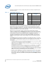
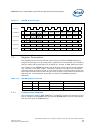
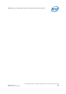
Table 115. SDRAM Burst Definitions
Burst Length Starting Column Address
Order of Accesses within a Burst
Type = Sequential Type = Interleaved
2A0
00-1 0-1
11-0 1-0