


Intel
®
IXP42X Product Line of Network Processors and IXC1100 Control Plane Processor
September 2006 DM
Order Number: 252480-006US 393
General Purpose Input/Output (GPIO)—Intel
®
IXP42X product line and IXC1100 control plane
processors
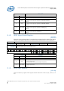
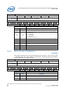
12.4.4 GPIO Interrupt Status Register
(GPISR)
This register is used to store status of a GP input interpreted as an interrupt. GP input
interrupts can be configured as active high, active low, rising edge, falling edge, or
transitional depending on the configuration of the GPIT[1:0]R register. A 1 read from
this register indicates a pending interrupt. Writing 1 back to this register will clear the
interrupt provided the interrupting condition no longer exists. The interrupts are all
masked in the Interrupt Controller block.
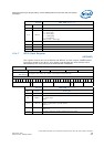
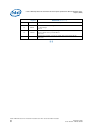
12.4.5 GP Interrupt Type Register 1
(GPIT1R)
This register describes how to interpret GPIO [7:0] as interrupts — either level or edge
— along with high, low, rising, falling, and transitional. Three bits describe each GPIO
pin, as described in the following table.
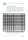
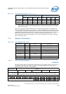
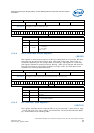
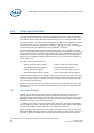
Register Name: GPINR
Hex Offset Address: 0xC800 4008 Reset Hex Value: 0x00000000
Register
Description:
This register is used to monitor input pins.
Access: Read.
31 16 15 0
(Reserved) IN_LEV
Register
GPINR
Bits Name Description
31:16 - Not used. Ignored on writes and driven logic 0 on reads.
15:0 IN_LEV
Level of general purpose inputs 15-0
1 = 1 on GPIO
0 = 0 on GPIO
Reset = 0x0
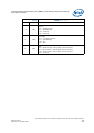
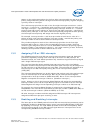
Register Name: GPISR
Hex Offset Address: 0xC800 400C Reset Hex Value: 0x00000000
Register
Description:
This register is used to store status of interrupts received on GP input pins.
Access: Read/Write.
31 16 15 13 12 0
(Reserved) Not Used INT_STAT
Register
GPISR
Bits Name Description
31:16 Not used. Ignored on writes and driven logic ‘0’ on reads.
15:13 Not used.
12:0 INT_STAT
1 = Interrupt pending.
0 = No interrupt pending.