


Intel
®
IXP42X Product Line of Network Processors and IXC1100 Control Plane Processor
September 2006 DM
Order Number: 252480-006US 517
Universal Serial Bus (USB) v1.1 Device Controller—Intel
®
IXP42X product line and IXC1100
control plane processors
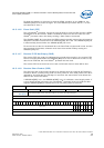
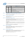
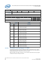
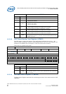
18.5.19 UDC Interrupt Control Register 1 (UICR1)
The UICR1 contains eight control bits to enable/disable interrupt service requests from
endpoints 8 through 15. The UICR1 bits are reset to 1 so interrupts are not generated
on initial system reset.
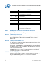
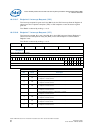
18.5.19.1 Interrupt Mask Endpoint x (IMx), where x is 8 through 15.
The UICR1[IMx] bit is used to mask or enable the corresponding endpoint interrupt
request, USIR1[IRx]. When the mask bit is set, the interrupt is masked and the
corresponding bit in the USIR1 register is not allowed to be set.
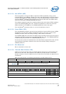
When the mask bit is cleared and an interruptible condition occurs in the endpoint, the
appropriate interrupt bit is set. Programming the mask bit to a 1 does not affect the
current state of the interrupt bit. It only blocks future 0-to-1 transitions of the interrupt
bit.
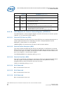
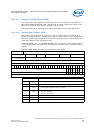
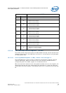
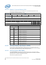
Register UICR0
Bits Name Description
31:8 Reserved for future use.
7IM7
Interrupt Mask for Endpoint 7.
0 = Receive interrupt enabled.
1 = Receive interrupt disabled.
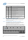
6IM6
Interrupt Mask for Endpoint 6.
0 = Transmit interrupt enabled.
1 = Transmit interrupt disabled.
5IM5
Interrupt mask for Endpoint 5.
0 = Transmit interrupt enabled.
1 = Transmit interrupt disabled.
4IM4
Interrupt mask for Endpoint 4.
0 = Receive Interrupt enabled.
1 = Receive Interrupt disabled.
3IM3
Interrupt mask for Endpoint 3.
0 = Transmit interrupt enabled.
1 = Transmit interrupt disabled.
2IM2
Interrupt Mask for Endpoint 2.
0 = Receive interrupt enabled.
1 = Receive interrupt disabled.
1IM1
Interrupt Mask for Endpoint 1.
0 = Transmit interrupt enabled.
1 = Transmit interrupt disabled.
0IM0
Interrupt mask for endpoint 0.
0 = Endpoint zero interrupt enabled.
1 = Endpoint zero interrupt disabled.