


Intel
®
IXP42X Product Line of Network Processors and IXC1100 Control Plane Processor
September 2006 DM
Order Number: 252480-006US 469
Universal Serial Bus (USB) v1.1 Device Controller—Intel
®
IXP42X product line and IXC1100
control plane processors
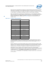
Packets are assembled into groups to produce transactions. Transactions fall into four
groups:
Endpoint 0 is used only to communicate the control transactions that configure the
UDC. Endpoint 0s responsibilities include:
The UDC uses a dual-port memory to support FIFO operations. Each Bulk and
Isochronous Endpoint FIFO structure is double-buffered to enable the endpoint to
process one packet as it assembles another. The Intel XScale
®
processor can fill and
empty the FIFOs. An interrupt is generated when a packet has been received.
Interrupts are also generated when the FIFO encounters a short packet or zero-length
packet. Endpoint 0 has a 16-entry-long, 8-bit-wide FIFO that can only be read or
written by the Intel XScale
®
processor.
For endpoints 1-15, the UDC uses its dual-ported memory to hold data for a Bulk OUT
transaction while the transaction is checked for errors. If the Bulk OUT transaction data
is invalid, the UDC sends a NAK handshake to request the host to resend the data. The
software is not notified that the OUT data is invalid until the Bulk OUT data is received
and verified. If the host sends a NAK handshake in response to a Bulk IN data
transmission, the UDC resends the data. Because the FIFO maintains a copy of the
data, the software does not have to reload the data.
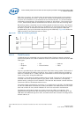
The external pins dedicated to the UDC interface are UDC+ and UDC-. The USB
protocol uses differential signalling between the two pins for half-duplex data
transmission. A 1.5-KΩ, pull-up resistor must be connected to the USB cable’s D+
signal to pull the UDC+ pin high when it is not driven. Pulling the UDC+ pin high when
it is not driven allows the UDC to be a high-speed, 12-Mbps device and provides the
correct polarity for data transmission.
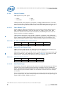
The serial bus uses differential signalling to transmit multiple states simultaneously.
These states are combined to produce transmit data and various bus conditions,
including:
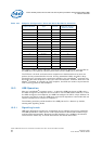
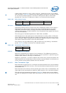
18.2 Device Configuration
The configuration of the Universal Serial Bus V 1.1 Device Controller is shown in
Table 160.
• Bulk • Control
• Interrupt • Isochronous
• Connection • Address assignment • Endpoint configuration
• Bus enumeration • Disconnection
•Idle •Resume •Start of Packet
• End of Packet • Disconnect • Connect
• Reset