


8-4 March, 2003 Developer’s Manual
Intel
®
80200 Processor based on Intel
®
XScale
™
Microarchitecture
System Management
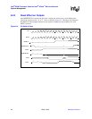
8.2.2 Reset Effect on Outputs
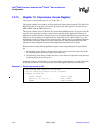
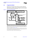
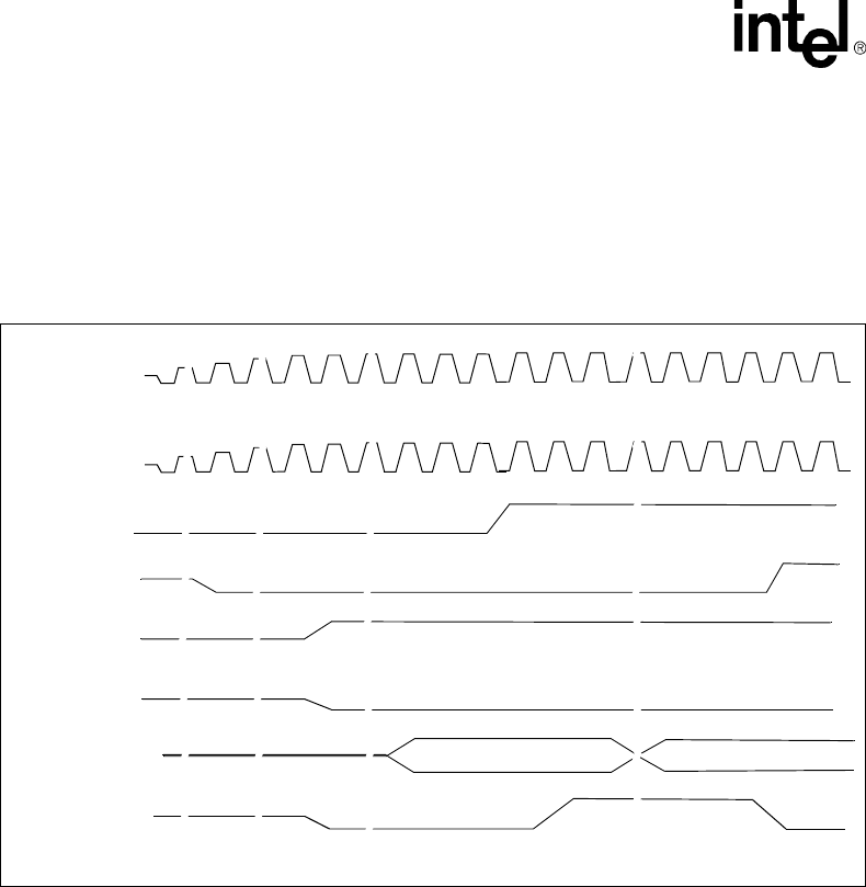
After RESETOUT# is asserted, the processor’s output pins are driven to a well-defined state.
Critical bus signals receive a ‘0’ or ‘1’ value, as shown in Figure 8-2. This figure also illustrates
that HOLD is acknowledged during the reset sequence. Output pins only transition if a valid
MCLK is present.
Figure 8-2. Pin State at Reset
MCLK
CLK
RESET#
RESETOUT#
ADS#
PWRSTATUS
HOLD
HLDA
∼
∼
∼
∼
∼
∼
∼
∼
∼
∼
∼
∼
∼
∼
∼
∼
∼
∼
∼
∼
∼
∼
∼
∼
∼
∼
∼
∼
∼
∼
∼
∼
∼
∼
∼
∼
∼
∼
∼
∼
∼
∼
∼
∼
∼
∼
∼
∼
∼
∼
∼
∼
∼
∼
∼
∼
∼
∼
∼
∼
∼
∼
∼
∼