


10-4 March, 2003 Developer’s Manual
Intel
®
80200 Processor based on Intel
®
XScale
™
Microarchitecture
External Bus
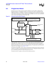
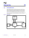
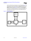
10.2.1 Request Bus
The request bus issues read or write requests from the Intel
®
80200 processor or other bus master
to the chipset or memory controller. Each request takes two MCLK cycles. All signals should be
sampled on the rising edge of MCLK. No data is ever transferred on the request bus.
On the first cycle, ADS#/LEN[2], Lock/LEN[1], and W/R#/LEN[0] are used to carry the ADS#,
Lock, and W/R# signals. A valid request is indicated by the ADS# signal being asserted low. On
that same clock edge, the sampled value of A is the most-significant 16 bits of the 32-bit address of
the request, W/R# indicates whether the request is a read or write from the Intel
®
80200 processor,
and the Lock pin indicates whether there is an atomic pair of operations outstanding.
On the second cycle of a request, ADS#/LEN[2], Lock/LEN[1], and W/R#/LEN[0] are used to
carry LEN[2:0]. LEN is used to indicate the number of data bytes associated with the request. See
Table 10-2 and Table 10-3 for information on how this signal is encoded. A has the least
significant 16 bits of the address for the request.
Lock is asserted for the read request that begins the atomic pair, and is asserted for each new
request up to (but not including) the write operation that ends the atomic pair. It is possible that
instruction fetches and instruction MMU page table walk requests occurs between the read and the
write of an atomic operation, but no other requests are made. Details of the lock mechanism and its
interaction with the multimaster logic is described below.
A bus master may have at most four requests outstanding at any time. That is: a bus master may
issue up to four requests before receiving back any data. For more information, see Section 10.3.7,
“Pipelined Accesses” on page 10-21.
10.2.1.1 Intel
®
80200 Processor Use of the Request Bus
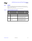
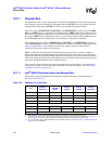
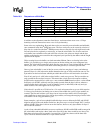
The possible sizes and alignments of read and write requests that can be issued are shown in
Table 10-2 and Table 10-3.
Table 10-2. Requests on a 64-bit Bus
LEN
1
1. LEN of 000, 001, or 010 should be treated as a LEN of 011 if directed to a slave that implements ECC.
Number of
Data Bytes
Number of
Data Bus
Cycles
Used for
Reads?
Used for
Writes?
Address
Alignment
000 1 1 Y Y Any Address
001 2 1 Y Y A[0] = “0”
010 4 1 Y Y A[1:0] = “00”
011 8 1 Y
2
2. An 8-byte read will only occur if ECC is enabled; it will occur as part of read-modify-write transactions (see Section 11.2,
“ECC” on page 11-1). If ECC is not enabled, the Intel
®
80200 processor will never perform an 8-byte read.
Y A[2:0] = “000”
100 Not Used in 64-bit Bus Mode
101 16 2 N Y A[3:0] = “0000”
110 32 4 Y N A[1:0] = “00”
3
3. On a 32-byte load, A[4:2] carries information for Critical Word First logic. See Section 10.2.3, “Critical Word First” on
page 10-7 for more information.
111 Not Used in 64-bit Bus Mode