C-10 March, 2003 Developer’s Manual
Intel
®
80200 Processor based on Intel
®
XScale
™
Microarchitecture
Test Features
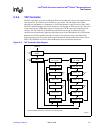
C.2.5.9. Update-DR State
The Boundary-Scan register is provided with a latched parallel output. This output prevents
changes at the parallel output while data is shifted in response to the extest, sample/preload
instructions. When the Boundary-Scan register is selected while the TAP controller is in the
Update-DR state, data is latched onto the Boundary-Scan register’s parallel output from the
shift-register path on the falling edge of TCK. The data held at the latched parallel output does not
change unless the controller is in this state.
While the TAP controller is in this state, all of the test data register’s shift-register bit positions
selected by the current instruction retain their previous values.
The instruction does not change while the TAP controller is in this state.
When the TAP controller is in this state and TMS is held high on the rising edge of TCK, the
controller enters the Select-DR-Scan state. If TMS is held low on the rising edge of TCK, the
controller enters the Run-Test/Idle state.
C.2.5.10. Select-IR Scan State
This is a temporary controller state. The test data registers selected by the current instruction retain
their previous state. In this state, if TMS is held low on the rising edge of TCK, the controller
moves into the Capture-IR state and a scan sequence for the instruction register is initiated. If TMS
is held high on the rising edge of TCK, the controller moves to the Test-Logic-Reset state.
The instruction does not change in this state.
C.2.5.11. Capture-IR State
When the controller is in the Capture-IR state, the shift register contained in the instruction register
loads the fixed value 0001
2
on the rising edge of TCK.
The test data register selected by the current instruction retains its previous value during this state.
The instruction does not change in this state. While in this state, holding TMS high on the rising
edge of TCK causes the controller to enter the Exit1-IR state. If TMS is held low on the rising edge
of TCK, the controller enters the Shift-IR state.
C.2.5.12. Shift-IR State
When the controller is in this state, the shift register contained in the instruction register is
connected between TDI and TDO and shifts data one bit position nearer to its serial output on each
rising edge of TCK. The test data register selected by the current instruction retains its previous
value during this state. The instruction does not change.
If TMS is held high on the rising edge of TCK, the controller enters the Exit1-IR state. If TMS is
held low on the rising edge of TCK, the controller remains in the Shift-IR state.


