


Developer’s Manual March, 2003 6-9
Intel
®
80200 Processor based on Intel
®
XScale
™
Microarchitecture
Data Cache
6.3 Data Cache and Mini-Data Cache Control
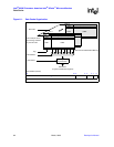
6.3.1 Data Memory State After Reset
After processor reset, both the data cache and mini-data cache are disabled, all valid bits are set to
zero (invalid), and the round-robin bit points to way 31. Any lines in the data cache that were
configured as data RAM before reset are changed back to cacheable lines after reset, i.e., there are
32 KBytes of data cache and zero bytes of data RAM.
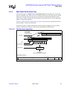
6.3.2 Enabling/Disabling
The data cache and mini-data cache are enabled by setting bit 2 in coprocessor 15, register 1
(Control Register). See Chapter 7, “Configuration”, for a description of this register and others.
Example 6-1 shows code that enables the data and mini-data caches. Note that the MMU must be
enabled to use the data cache.
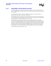
6.3.3 Invalidate & Clean Operations
Individual entries can be invalidated and cleaned in the data cache and mini-data cache via
coprocessor 15, register 7. Note that a line locked into the data cache remains locked even after it
has been subjected to an invalidate-entry operation. This will leave an unusable line in the cache
until a global unlock has occurred. For this reason, do not use these commands on locked lines.
This same register also provides the command to invalidate the entire data cache and mini-data
cache. Refer to Table 7-12, “Cache Functions” on page 7-11 for a listing of the commands. These
global invalidate commands have no effect on lines locked in the data cache. Locked lines must be
unlocked before they can be invalidated. This is accomplished by the Unlock Data Cache
command found in Table 7-14, “Cache Lockdown Functions” on page 7-14.
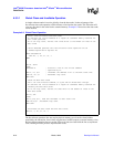
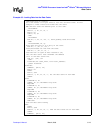
Example 6-1. Enabling the Data Cache
enableDCache:
MCR p15, 0, r0, c7, c10, 4; Drain pending data operations...
; (see Chapter 7.2.8, Register 7: Cache functions)
MRC p15, 0, r0, c1, c0, 0; Get current control register
ORR r0, r0, #4 ; Enable DCache by setting ‘C’ (bit 2)
MCR p15, 0, r0, c1, c0, 0; And update the Control register