


Developer’s Manual March, 2003 13-9
Intel
®
80200 Processor based on Intel
®
XScale
™
Microarchitecture
Software Debug
13.6 HW Breakpoint Resources
The Intel
®
80200 processor debug architecture defines two instruction and two data breakpoint
registers, denoted IBCR0, IBCR1, DBR0, and DBR1.
The instruction and data address breakpoint registers are 32-bit registers. The instruction
breakpoint causes a break before execution of the target instruction. The data breakpoint causes a
break after the memory access has been issued.
In this section Modified Virtual Address (MVA) refers to the virtual address ORed with the PID.
Refer to section XXX for more details on the PID. The processor does not OR the PID with the
specified breakpoint address prior to doing address comparison. This must be done by the
programmer and written to the breakpoint register as the MVA. This applies to data and instruction
breakpoints.
13.6.1 Instruction Breakpoints
The Debug architecture defines two instruction breakpoint registers (IBCR0 and IBCR1). The
format of these registers is shown in Table 13-3., Instruction Breakpoint Address and Control
Register (IBCRx). In ARM mode, the upper 30 bits contain a word aligned MVA to break on. In
Thumb* mode, the upper 31 bits contain a half-word aligned MVA to break on. In both modes, bit
0 enables and disables that instruction breakpoint register. Enabling instruction breakpoints while
debug is globally disabled (DCSR.GE=0) may result in unpredictable behavior.
An instruction breakpoint generates a debug exception before the instruction at the address
specified in the ICBR executes. When an instruction breakpoint occurs, the processor sets the
DBCR.moe bits to 0b001.
Software must disable the breakpoint before exiting the handler. This allows the breakpointed
instruction to execute after the exception is handled.
Single step execution is accomplished using the instruction breakpoint registers and must be
completely handled in software (either on the host or by the debug handler).
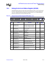
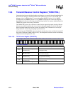
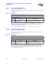
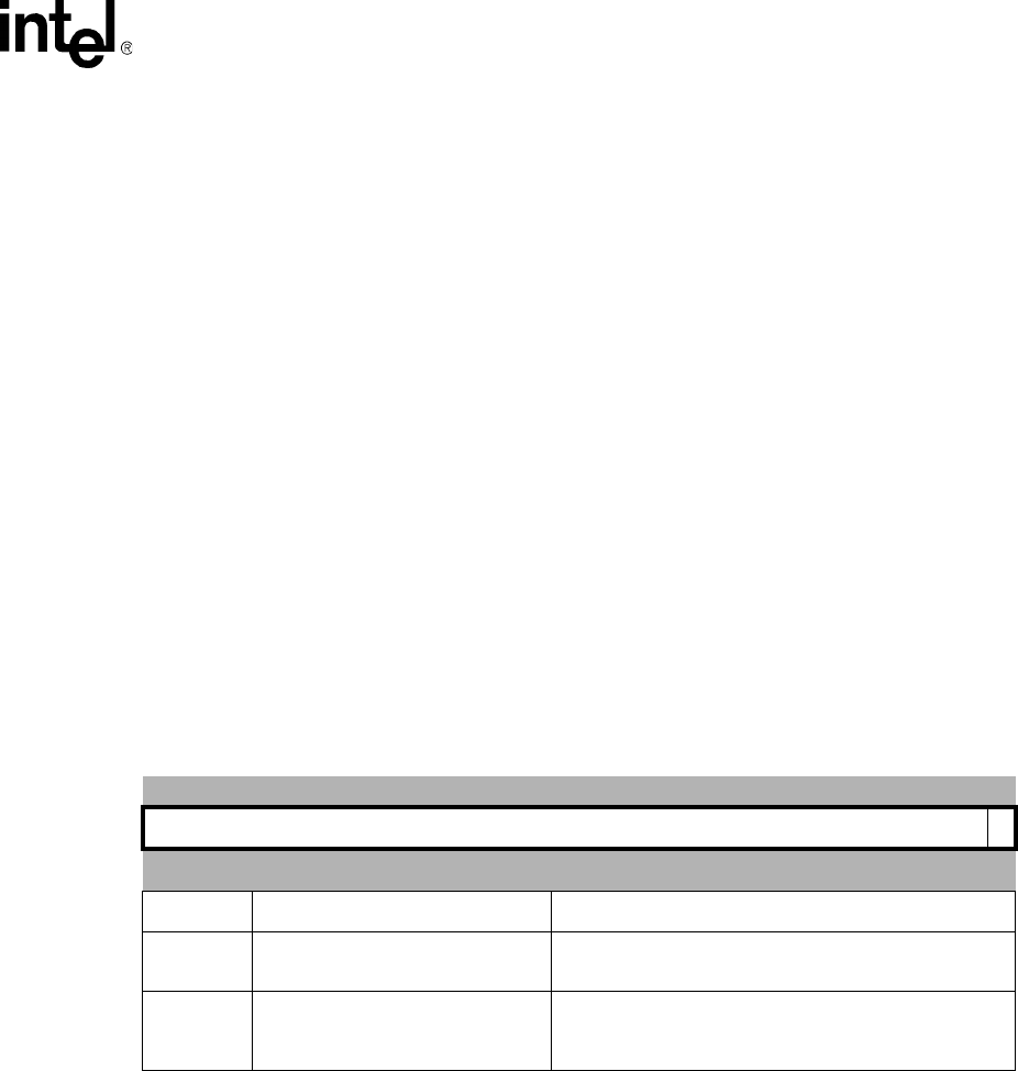
Table 13-3. Instruction Breakpoint Address and Control Register (IBCRx)
31 30 29 28 27 26 25 24 23 22 21 20 19 18 17 16 15 14 13 12 11 10 9 8 7 6 5 4 3 2 1 0
IBCRx E
reset value: unpredictable address, disabled
Bits Access Description
31:1 Read / Write
Instruction Breakpoint MVA
in ARM* mode, IBCRx[1] is ignored
0 Read / Write
IBCRx Enable (E) -
0 = Breakpoint disabled
1 = Breakpoint enabled