


Developer’s Manual March, 2003 10-3
Intel
®
80200 Processor based on Intel
®
XScale
™
Microarchitecture
External Bus
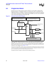
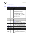
10.2 Signal Description
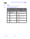
Table 10-1. Intel
®
80200 Processor based on Intel
®
XScale
™
Microarchitecture Bus Signals
Signal Width I/O Function
MCLK 1 I
bus clock (note: all bus activity is triggered by the rising edge of this
clock).
Request Bus
ADS#/LEN[2] 1 O
During the first cycle of the issue phase: this signal indicates the start
of a bus request.
During the second cycle of the issue phase: this signal is the MSB of
a value which indicates the length of the transaction.
Lock/LEN[1] 1 O
During the first cycle of the issue phase: this signal indicates whether
the current transaction is part of an atomic read-write pair.
During the second cycle of the issue phase: this signal is the middle
bit of a value which indicates the length of the transaction.
W/R#/LEN[0] 1 O
During the first cycle of the issue phase: this signal indicates whether
the current transaction is a write (W/R# = 1) or a read (W/R# = 0).
During the second cycle of the issue phase: this signal is the LSB of a
value which indicates the length of the transaction.
A16O
During the first cycle of the issue phase: this signal carries the upper
16 bits of the address for the access.
During the second cycle of the issue phase: this signal carries the
lower 16 bits of the address.
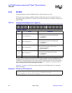
Data Bus
D64I/OData Bus
BE# 8 O Byte Enables for writes (timing same as Data)
DCB 8 I/O Data Check Bits for ECC (timing same as Data)
CWF 1 I
Critical Word First: Indicates the order in which the current 32-byte
read burst is returning. See Section 10.2.3, “Critical Word First” on
page 10-7 for more information on this signal.
This pin must be asserted at the same time as the DValid of the first
cycle of returning data for a given read transaction. It is ignored at all
other times.
DValid 1 I
Indicates that two cycles later there is an Intel
®
80200 Processor data
cycle on D, DCB, and possibly BE# (either read sampled by the
Intel
®
80200 processor or write driven by the Intel
®
80200 processor)
Abort 1 I
Asserted with DValid, indicates that the Intel
®
80200 processor
transaction next in order on the Data bus has been aborted (timing
same as DValid)
Multimaster Support
Hold 1 I
Input that tells the Intel
®
80200 processor to float the following pins:
ADS#, A, W/R#, Lock
HldA 1 O
Asserted when the Intel
®
80200 processor has completed the
transition to hold mode in response to Hold.
Configuration
CWF/
DBusWidth
1
(shared with
CWF)
I
When the Intel
®
80200 processor is in reset, this pin functions as
DBusWidth: the Intel
®
80200 processor samples this pin to find the
bus width in use. If it is 1, then the system is operating with a 32-bit
bus, otherwise the Intel
®
80200 processor uses a 64-bit bus. This pin
is sampled by the Intel
®
80200 processor while RESETOUT# is
asserted.