


Developer’s Manual March, 2003 11-5
Intel
®
80200 Processor based on Intel
®
XScale
™
Microarchitecture
Bus Controller
11.4 Programmer Model
The BCU registers reside in Coprocessor 13 (CP13). They may be accessed/manipulated with the
MCR, MRC, STC, and LDC instructions. The CRn field of the instruction denotes the register
number to be accessed. Field CRm must be set to 1. The opcode_1, and opcode_2 fields of the
instruction should be zero. Access to CP13 may be controlled using the Coprocessor Access
Register (see Section 7.2.13, “Register 13: Process ID” on page 7-16).
An instruction that modifies a BCU register is guaranteed to take effect before the next instruction
executes.
11.4.1 BCU Control Registers
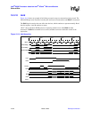
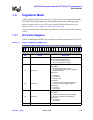
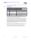
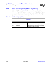
The BCU Control Register (BCUCTL) allows software to view and control the behavior of the BCU.
Table 11-2. BCUCTL (Register 0) (Sheet 1 of 2)
31 30 29 28 27 26 25 24 23 22 21 20 19 18 17 16 15 14 13 12 11 10 9 8 7 6 5 4 3 2 1 0
T
P
E
V
E
1
E
0
E
E
S
C
S
R
reset value: all implemented bits are 0
Bits Access Description
31 Read / Write-ignored
TP - Transactions Pending
Indicates whether the BCU is idle
0 = no memory transactions pending
1 = one or more transactions pending
30 Read / Write
EV - Error Overflow
Read Values:
0 = no unlogged errors have occurred
1 = errors have occurred beyond those logged in
ELOG0 and ELOG1
Write Values:
0 = no change
1 = clear this bit
29 Read / Write
E1 - ELOG1 is valid
Read Values:
0 = contents of ELOG1 should be disregarded
1 = Error occurred and is logged in ELOG1
Write Values:
0 = no change
1 = clear this bit
28 Read / Write
E0 - ELOG0 is valid
Read Values:
0 = contents of ELOG0 should be disregarded
1 = Error occurred and is logged in ELOG0
Write Values:
0 = no change
1 = clear this bit
27:4 Read-unpredictable / Write-as-0 reserved