


Developer’s Manual March, 2003 7-3
Intel
®
80200 Processor based on Intel
®
XScale
™
Microarchitecture
Configuration
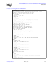
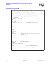
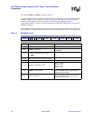
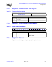
The format of LDC and STC is shown in Table 7-2. LDC and STC follow the programming notes
in the ARM Architecture Reference Manual.
LDC and STC transfer a single 32-bit word between a coprocessor register and memory. These
instructions do not allow the programmer to specify values for opcode_1, opcode_2, or Rm; those
fields implicitly contain zero.
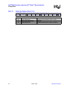
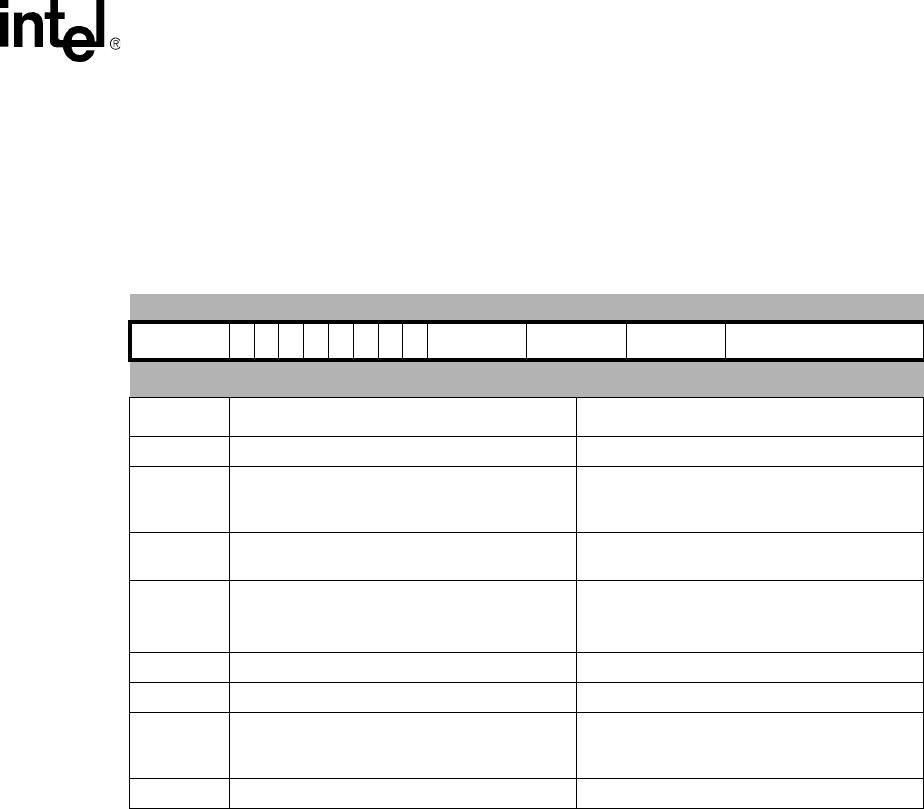
Table 7-2. LDC/STC Format
31 30 29 28 27 26 25 24 23 22 21 20 19 18 17 16 15 14 13 12 11 10 9 8 7 6 5 4 3 2 1 0
cond 1 1 0 P U N W L Rn CRd cp_num 8_bit_word_offset
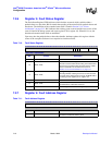
Bits Description Notes
31:28 cond - ARM* condition codes -
24:23,21
P, U, W - specifies 1 of 3 addressing modes
identified by addressing mode 5 in the
ARM
Architecture Reference Manual
.
-
22
N - should be 0 for Intel
®
80200 processors.
Setting this bit to 1 has an undefined effect.
20
L - Load or Store
0 = STC
1 = LDC
-
19:16 Rn - specifies the base register -
15:12 CRd - specifies the coprocessor register -
11:8 cp_num - coprocessor number
0b1111 = Undefined Exception
0b1110 = CP14
0b1101 = CP13
7:0 8-bit word offset -