


C-8 March, 2003 Developer’s Manual
Intel
®
80200 Processor based on Intel
®
XScale
™
Microarchitecture
Test Features
C.2.5.1. Test Logic Reset State
In this state, test logic is disabled to allow normal operation of the Intel
®
80200 processor. Test
logic is disabled by loading the idcode register. No matter what the state of the controller, it enters
Test-Logic-Reset state when the TMS input is held high (1) for at least five rising edges of TCK.
The controller remains in this state while TMS is high. The TAP controller is also forced to enter
this state by enabling TRST#.
If the controller exits the Test-Logic-Reset controller states as a result of an erroneous low signal
on the TMS line at the time of a rising edge on TCK (for example, a glitch due to external
interference), it returns to the test logic reset state following three rising edges of TCK with the
TMS line at the intended high logic level. Test logic operation is such that no disturbance is caused
to on-chip system logic operation as the result of such an error.
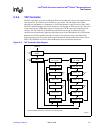
C.2.5.2. Run-Test/Idle State
The TAP controller enters the Run-Test/Idle state between scan operations. The controller remains
in this state as long as TMS is held low. In the Run-Test/Idle state the
runbist instruction is
performed; the result is reported in the RUNBIST register. Instructions that do not call functions
generate no activity in the test logic while the controller is in this state. The instruction register and
all test data registers retain their current state. When TMS is high on the rising edge of TCK, the
controller moves to the Select-DR-Scan state.
C.2.5.3. Select-DR-Scan State
The Select-DR-Scan state is a temporary controller state. The test data registers selected by the
current instruction retain their previous state. If TMS is held low on the rising edge of TCK when
the controller is in this state, the controller moves into the Capture-DR state and a scan sequence
for the selected test data register is initiated. If TMS is held high on the rising edge of TCK, the
controller moves into the Select-IR-Scan state.
The instruction does not change while the TAP controller is in this state.
C.2.5.4. Capture-DR State
When the controller is in this state and the current instruction is sample/preload, the
Boundary-Scan register captures input pin data on the rising edge of TCK.Test data registers that
do not have parallel input are not changed. Also if the sample/preload instruction is not selected
while in this state, the Boundary-Scan registers retain their previous state.
The instruction does not change while the TAP controller is in this state.
If TMS is high on the rising edge of TCK, the controller enters the Exit1-DR. If TMS is low on the
rising edge of TCK, the controller enters the Shift-DR state.