13-28 March, 2003 Developer’s Manual
Intel
®
80200 Processor based on Intel
®
XScale
™
Microarchitecture
Software Debug
13.13 Trace Buffer Entries
Trace buffer entries consist of either one or five bytes. Most entries are one byte messages
indicating the type of control flow change. The target address of the control flow change
represented by the message byte is either encoded in the message byte (like for exceptions) or can
be determined by looking at the instruction word (like for direct branches). Indirect branches
require five bytes per entry. One byte is the message byte identifying it as an indirect branch. The
other four bytes make up the target address of the indirect branch. The following sections describe
the trace buffer entries in detail.
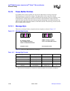
13.13.1 Message Byte
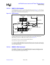
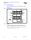
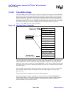
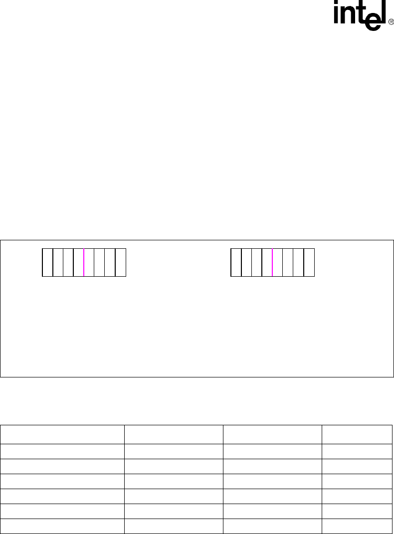
There are two message formats, (exception and non-exception) as shown in Figure 13-7.
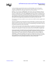
Table 13-17 shows all of the possible trace messages.
Figure 13-7. Message Byte Formats
07
VM CCCCVV
07
MM CCCCMM
Exception Format
Non-exception Format
M = Message Type Bit
VVV = exception vector[4:2]
CCCC = Incremental Word Count
MMMM = Message Type Bits
CCCC = Incremental Word Count
Table 13-17. Message Byte Formats
Message Name Message Byte Type Message Byte format # address bytes
Exception exception 0b0VVV CCCC 0
Direct Branch
a
a. Direct branches include ARM and THUMB bl, b
non-exception 0b1000 CCCC 0
Checkpointed Direct Branch
a
non-exception 0b1100 CCCC 0
Indirect Branch
b
b. Indirect branches include ARM ldm, ldr, and dproc to PC; ARM and THUMB bx, blx(1) and blx(2); and THUMB pop.
non-exception 0b1001 CCCC 4
Checkpointed Indirect Branch
b
non-exception 0b1101 CCCC 4
Roll-over non-exception 0b1111 1111 0


