


B-2
Cisco ASDM User Guide
OL-16647-01
Appendix B Troubleshooting
Testing Your Configuration
Step 1 To show ICMP packet information for pings to the security appliance interfaces, enter the following
command:
hostname(config)# debug icmp trace
Step 2 To set system log messages to be sent to Telnet or SSH sessions, enter the following command:
hostname(config)# logging monitor debug
You can alternately use the logging buffer debug command to send log messages to a buffer, and then
view them later using the show logging command.
Step 3 To send the system log messages to a Telnet or SSH session, enter the following command:
hostname(config)# terminal monitor
Step 4 To enable system log messages, enter the following command:
hostname(config)# logging on
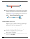
The following example shows a successful ping from an external host (209.165.201.2) to the security
appliance outside interface (209.165.201.1):
hostname(config)# debug icmp trace
Inbound ICMP echo reply (len 32 id 1 seq 256) 209.165.201.1 > 209.165.201.2
Outbound ICMP echo request (len 32 id 1 seq 512) 209.165.201.2 > 209.165.201.1
Inbound ICMP echo reply (len 32 id 1 seq 512) 209.165.201.1 > 209.165.201.2
Outbound ICMP echo request (len 32 id 1 seq 768) 209.165.201.2 > 209.165.201.1
Inbound ICMP echo reply (len 32 id 1 seq 768) 209.165.201.1 > 209.165.201.2
Outbound ICMP echo request (len 32 id 1 seq 1024) 209.165.201.2 > 209.165.201.1
Inbound ICMP echo reply (len 32 id 1 seq 1024) 209.165.201.1 > 209.165.201.2
This example shows the ICMP packet length (32 bytes), the ICMP packet identifier (1), and the ICMP
sequence number (the ICMP sequence number starts at 0 and is incremented each time that a request is
sent).
Pinging Security Appliance Interfaces
To test whether the security appliance interfaces are up and running and that the security appliance and
connected routers are operating correctly, you can ping the security appliance interfaces. To ping the
security appliance interfaces, perform the following steps:
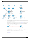
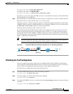
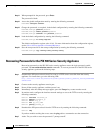
Step 1 Draw a diagram of your single-mode security appliance or security context that shows the interface
names, security levels, and IP addresses.
Note Although this procedure uses IP addresses, the ping command also supports DNS names and
names that are assigned to a local IP address with the name command.
The diagram should also include any directly connected routers, and a host on the other side of the router
from which you will ping the security appliance. You will use this information in this procedure and in
the procedure in “Pinging Through the Security Appliance” section on page B-4. For example: