


78
CHAPTER 3 CLOCK GENERATOR AND CONTROLLER
3.3 Standby Control Register (STCR)
The standby control register (STCR) is used to control standby operation and specify
the oscillation stabilization wait time.
■
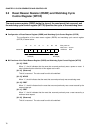
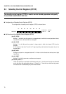
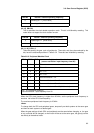
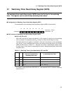
Configuration of Standby Control Register (STCR)
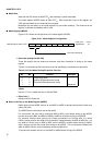
The configuration of standby control register (STCR) is shown below:
■
Bit Functions of the Standby Control Register (STCR)
[bit 07] STOP
Writing "1" to this bit puts the system in a stopped state in which the internal peripheral clock,
internal CPU clock, and oscillation are stopped.
[bit 06] SLEP
Writing "1" to this bit puts the system in sleep state in which the internal CPU clock is
stopped.
If 1 is written to both bits 7 and 6, bit 7 is given priority and therefore the system is put in a
stopped state.
[bit 05] HIZX
Putting the system in a stopped state with "1" written to this bit sets the device pins at high
impedance.
[bit 04] SRST
Writing "0" to this bit generates a software reset request.
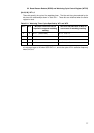
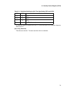
[bit 03, 02] OSC1, 0
These bits specify the oscillation stabilization wait time. The bits and the wait time selected
by the bits have the relationships shown in Table 3.3.1. These bits are initialized by power-
on reset but are not affected by any other reset causes.
07 06 05 04 03 02 01 00
00000481
H
STOP SLEP HIZX SRST OSC1 OSC0 000111-- R/W
Access
Initial value