


102
CHAPTER 3 CLOCK GENERATOR AND CONTROLLER
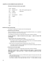
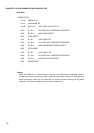
[Example]
<Notes>
• When the PONR bit is 1, assume that the contents of the other bits are undefined. When it
is required to check reset sources, place a power-on reset check instruction at the beginning.
• Check instructions other than the instruction for power-on reset checking can be placed
anywhere. Priorities are determined in the order of placement.
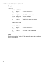
RESET-ENTRY
LDI:20 #RSRR, R10
LDI:8 #10000000B, R2
LDUB @R10, R1 ; GET RSRR VALUE INTO R1
MOV R1, R10 ; R10 USED AS A TEMPORARY REGISTER
AND R2, R10 ; WAS PONR RESET?
BNE PONR-RESET
LSR #1, R2 ; POINT NEXT BIT
MOV R1, R10 ; R10 USED AS A TEMPORARY REGISTER
AND R2, R10 ; WAS HARDWARE STANDBY RESET?
BNE HSTB-RESET
LSR #1, R2 ; POINT NEXT BIT
MOV R1, R10 ; R10 USED AS A TEMPORARY REGISTER
AND R2, R10 ; WAS WATCH DOG RESET?
BNE WDOG-RESET
: