


196
CHAPTER 4 BUS INTERFACE
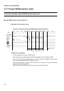
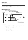
4.19 Program Example for External Bus Operation
This section provides a simple program example for external bus operation.
■
Program Specification Examples for External Bus Operation
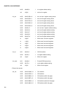
Register settings are as follows:
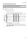
❍
Areas
• Area 0 (AMD0): 16 bits, usual bus, automatic wait 0
• Area 1 (AMD1): 16 bits, usual bus, automatic wait 2
• Area 2 (AMD32): 16 bits, usual bus, automatic wait 1
• Area 3 (AMD32): 16 bits, usual bus, automatic wait 1
• Area 4 (AMD4): 16 bits, DRAM, page size 256, 1CAS/2WE, with wait, CBR refresh
• Area 5 (AMD5): 16 bits, DRAM, page size 512, 2CAS/1WE, without wait, CBR refresh
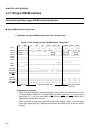
❍
Other buses
• Refresh (RFCR): without wait, 1/8 setting
• External pin (EPCR0): external RDY reception, arbitration by BRQ and BGRNTX
• External pin (DSCR): DRAM pin setting
• Little endian (LER): area 2
Also, observe the following notes:
• Pins MD2, MD1, and MD0 are "001", and external vector is in 16-bit mode.
• Before setting the mode register (MODR), set area 0 to the same bus width.
• Set area 1 to area 5 such that overlapping does not occur.
■
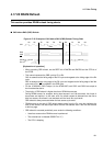
Program Example for External Bus Operation
For explanation, this program writes to the byte register in bytes and the half-word register in
half-words.
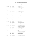
***** Program example *****
//Each register setting
init_epcr ldi:20 #0xffff,r0 //
//
External pin setting
External RDY wait, bus arbitration by
BRQ and BGRNTX
ldi:20 #0x628,r1 // epcr0 register address setting
sth r0,@r1 // Write to epcr0 register
init_dscr ldi:8 #0xff,r0 //
//
DRAM pin setting
RAS, CAS, WE
ldi:20 #0x625,r1 // dscr register address setting