


250
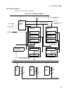
CHAPTER 10 UART
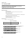
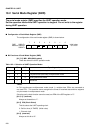
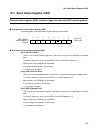
10.3 Serial Control Register (SCR)
The serial control register (SCR) controls the transfer protocol used for serial
communication.
■
Configuration of Serial Control Register (SSR)
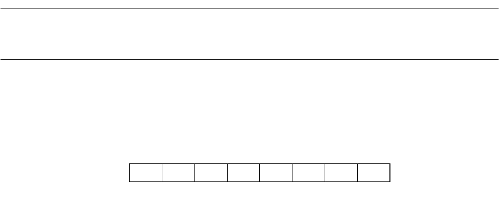
The configuration of the serial control register (SCR) is shown below:
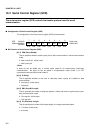
■
Bit Function of Serial Control Register (SSR)
[bit 7] PEN (Parity Enable)
This bit specifies whether to add a parity bit for data communication in serial communication
mode.
0: Add no parity bit. (Initial value)
1: Add a parity bit.
<Note>
A parity bit can be added only in normal mode (mode 0) for asynchronous (start-stop)
communication. No parity bit can be added in multiprocessor mode (mode 1) or CLK
synchronous communication mode (mode 2).
[bit 6] P (Parity)
This bit specifies whether to use even or odd parity when a parity bit is added for data
communication.
0: Even parity (Initial value)
1: Odd parity
[bit 5] SBL (Stop Bit Length)
This bit specifies the number of stop bits used as a frame end mark in asynchronous (start-
stop) communication mode.
0: One stop bit (Initial value)
1: Two stop bits
[bit 4] CL (Character Length)
This bit specifies the number of bits (data length) for a single transmitted frame.
0: 7-bit data (Initial value)
1: 8-bit data
76543210
SCR 00001E
H
Address:000022
H
PEN P SBL CL A/D REC RXE TXE 00000100
B
000026
H
R/W R/W R/W R/W R/W W R/W R/W
Initial value