


306
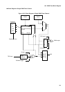
CHAPTER 14 PWM TIMER
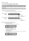
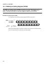
[bit 5] IREN: Interrupt request enable bit
This bit enables or disables interrupt requests.
[bit 4] IRQF: Interrupt request flag
When the interrupt cause selected by bits 3 and 2 (IRS1 and IRS0) is generated while bit 5
(IREN) is set to 1 (Enable), this bit is set to cause an interrupt request to the CPU. This
Executing an operation for setting the bit to 1 does not change the bit value.
DMA transfer also starts if DMA transfer activation has been selected.
This bit is cleared when "0" is written to it or by the clear signal from the DMAC.
Executing an operation for setting the bit to "1" does not change the bit value.
A Read Modify Write instruction reads "1" from this bit regardless of the bit value.
[bits 3, 2] IRS1, IRS0: Interrupt cause select bit
These bits select the cause that sets bit 4 (IRQF).
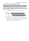
[bit 1] POEN: PWM output enable bit
Setting this bit to "1" enables PWM output.
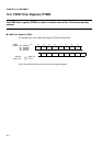
[bit 0] OSEL: PWM output polarity specification bit
This bit selects the polarity of PWM output.
This bit can be combined with bit 9 (PGMS) as shown below.
0 Disabled (initial value)
1 Enabled
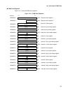
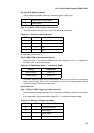
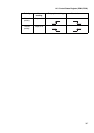
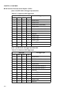
Table 14.3-4 Selection of Interrupt Causes
IRS1 IRS0 Interrupt cause
0 0 Software trigger, or trigger input (Initial value)
0 1 Occurrence of counter borrow (cycle matching)
1 0 Occurrence of duty cycle matching
1 1 Occurrence of counter borrow (cycle matching) or duty cycle
matching
0 General-purpose port (Initial value)
1 PWM output pin
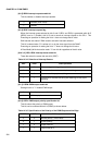
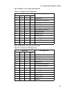
Table 14.3-5 Specification of the Polarity of the PWM Output and the Edge
PGMS OSEL
PWM output
0 0 Normal polarity (Initial value)
0 1 Inverse polarity
1 0 Output fixed to L
1 1 Output fixed to H