


83
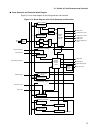
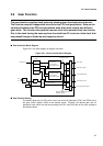
3.6 Gear Control Register (GCR)
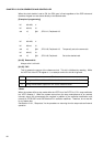
[bit 12] DBLON
This bit specifies the clock doubler operation mode. This bit is initialized by resetting. This
model does not support the clock doubler function.
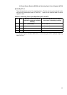
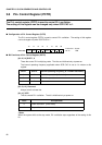
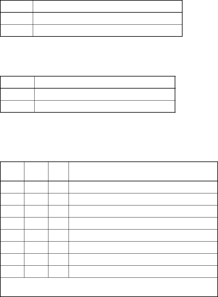
[bit 11, 10] PCK1, 0
These bits specify the gear cycle of peripherals. These bits, and the cycles selected by the
bits, have the relationships shown in Table 3.6.2. These bits are initialized by resetting.
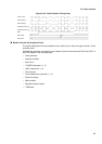
When the CPU clock frequency is higher than 25 MHz, set the peripheral clock frequency to
less than half of the CPU clock frequency.
The maximum peripheral clock frequency is 25 MHz.
<Note>
To change both the CPU and peripheral gears, temporarily set both systems to the same gear
and then set each system to a desired gear.
When the gear settings of both CPU and peripherals are the same before changing, or the gear
of only one side will be changed, or when both will be set to the same gear, the gear(s) can be
set directly to the desired value.
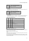
DBLAK Internal : external operating frequency
0 Operating at 1:1 [Initial value]
1 Operating at 2:1
DBLON Internal : external operating frequency
0 Operating at 1:1 [Initial value]
1 Operating at 2:1
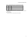
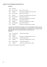
Table 3.6-2 Peripheral Machine Clock
PCK1 PCK0 CHC Peripheral machine clock
(source oscillation: input frequency from X0)
000PLL
× 1
010PLL
× 1/
2
100PLL
× 1/4
110PLL
×
1/8
0 0 1 Source oscillation
×
1/2
0 1 1 Source oscillation
×
1/2
×
1/2
1 0 1 Source oscillation
×
1/2
×
1/4
1 1 1 Source oscillation
×
1/2
×
1/8 [Initial value]
PLL: PLL oscillation frequency
Source oscillation: Input frequency from X0