


125
4.8 Area Mode Register 4 (AMD4)
4.8 Area Mode Register 4 (AMD4)
Area mode register 4 (AMD4) specifies the operation mode of chip select area 4 (area
specified by ASR4 and AMR4).
Area 4 allows the use of the DRAM interface.
■
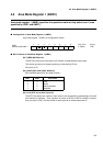
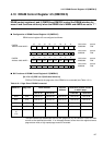
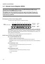
Configuration of Area Mode Register 4 (AMD4)
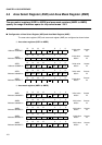
Area mode register 4 (AMD4) is configured as follows:
■
Bit Functions of Area Mode Register 4 (AMD4)
[bit 7] DRME (DRaM Enable bit)
The DRME bit selects the usual bus interface or DRAM interface for area 4.
0: Usual bus interface
1: DRAM interface
When the DRAM interface is used, more details must be specified via the DMCR (DRAM
control register), which is described later.
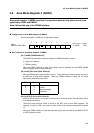
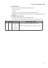
[bit 4 and 3] BW1 and 0 (Bus Width bit)
BW1 and BW0 specify the bus width of area 4. These bits have functions similar to those of
the BW bits of other AMD registers. When the DRAM interface is used, the bus width
specified by these bits is also valid.
[bit 2 to 0] WTC 2 to 0 (Wait Cycle bit)
WTC2 to WTC0 specify the number of wait cycles to be automatically inserted when area 4
is accessed via memory.
These bits have functions similar to those of the WTC bits of other AMD registers. By
resetting the bits to "000", the number of wait cycles to be inserted automatically becomes
"0".
When the DRAM interface is used because wait cycles are controlled by the DMCR, WTC2
to WTC0 become invalid.
76543210
AMD4
0623
H
DRME BW1 BW0 WTC2 WTC1 WTC0
0--00000 R/W
Address: 0000
Initial value
Access
BW1 BW0 Bus width
0
0
1
1
0
1
0
1
8 bits
16 bits
Setting disabled
Reserved