


145
4.16 Relationship between Data Bus Widths and Control Signals
❍
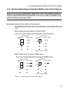
8-bit bus width
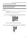
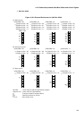
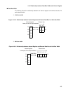
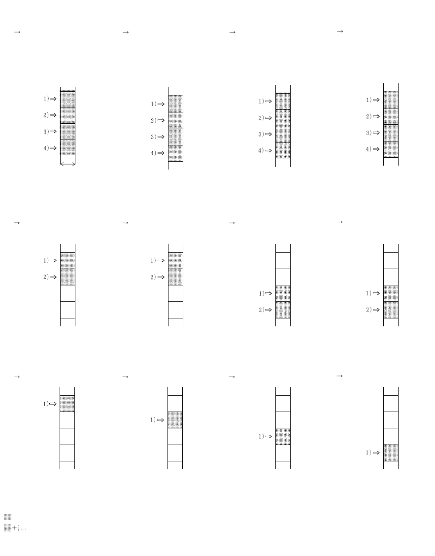
Figure 4.16-9 External Bus Access for 8-bit Bus Width
PA1/PA0 : Lower 2 bits of address specified by program
Output A1/A0 : Lower 2 bits of output address
: First byte location of output address
: Data byte location for access
1) to 4) : Bus access count
MSB LSB
8bit
PA1/PA0= '00' PA1/PA0= '01' PA1/PA0= '10' PA1/PA0= '11'
(a) (b) (c) (d)
00
01
10
11
00
01
10
11
00
01
10
11
00
01
10
11
00
01
10
11
00
01
10
11
00
01
10
11
00
01
10
11
00
01
10
11
00
01
10
11
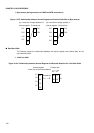
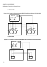
(A) Word access
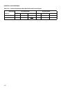
(B) Half-word access
(C) Byte access
1)Output A1/A0 = '00'
2)Output A1/A0 = '01'
3)Output A1/A0 = '10'
4)Output A1/A0 = '11'
1)Output A1/A0 = '00'
2)Output A1/A0 = '01'
3)Output A1/A0 = '10'
4)Output A1/A0 = '11'
1)Output A1/A0 = '00'
2)Output A1/A0 = '01'
3)Output A1/A0 = '10'
4)Output A1/A0 = '11'
1)Output A1/A0 = '00'
2)Output A1/A0 = '01'
3)Output A1/A0 = '10'
4)Output A1/A0 = '11'
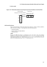
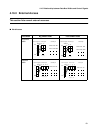
PA1/PA0= '00' PA1/PA0= '01' PA1/PA0= '10' PA1/PA0= '11'
(a) (b) (c) (d)
1)Output A1/A0 = '00'
2)Output A1/A0 = '01'
1)Output A1/A0 = '00'
2)Output A1/A0 = '01'
1)Output A1/A0 = '10'
2)Output A1/A0 = '11'
1)Output A1/A0 = '10'
2)Output A1/A0 = '11'
00
01
10
11
00
01
10
11
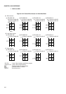
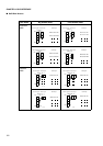
PA1/PA0= '00' PA1/PA0= '01' PA1/PA0= '10' PA1/PA0= '11'
(a) (b) (c) (d)
1)Output A1/A0 = '00' 1)Output A1/A0 = '01' 1)Output A1/A0 = '10' 1)Output A1/A0 = '11'