


82
CHAPTER 3 CLOCK GENERATOR AND CONTROLLER
3.6 Gear Control Register (GCR)
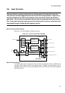
The gear control register (GCR) controls the gear functions of the CPU and peripheral
clocks.
■
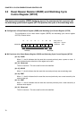
Configuration of the Gear Control Register (GCR)
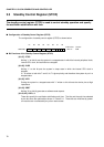
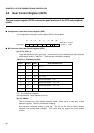
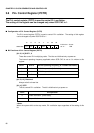
The configuration of the gear control register (GCR) is shown below:
■
Bit Functions of the Gear Control Register (GCR)
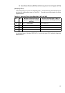
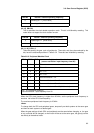
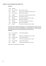
[bit 15,14] CCK1, 0
These bits specify the CPU gear cycle. The bits and the cycles selected by the bits have the
relationships shown in Table 3.6.1. These bits are initialized by resetting.
PLL: PLL oscillation frequency
Source oscillation: Input frequency from X0
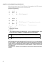
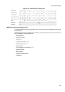
[bit 13] DBLAK
This bit indicates the clock doubler operation mode. Since the bit is read only, a write
attempt is ignored. This bit is initialized by resetting.
Bus frequency switching involves a time lag. This bit can be used to check whether
operation has actually been changed. This model does not support the clock doubler
function.
15 14 13 12 11 10 09 08
00000484
H
CCK1 CCK0 DBLAK DBLON PCK1 PCK0 CHC 110011-1 R/W
Initial value
Access
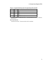
Table 3.6-1 CPU Machine Clock
CCK1 CCK0 CHC CPU machine clock
000PLL
× 1
010PLL
×
1/2
100PLL
×
1/4
110PLL
×
1/8
0 0 1 Source oscillation × 1
/
2
0 1 1 Source oscillation ×
1/2
×
1/2
1 0 1 Source oscillation
×
1/2
×
1/4
1 1 1 Source oscillation
×
1/2
×
1/8 [Initial value]