


242
CHAPTER 9 U-TIMER
In addition to a normal 2(n+1) cycle clock, an odd frequency clock can be set for the UART.
Setting 1 in UCC1 generates 2n+3 cycle clock pulses.
[Example of setting]
UTIMR = 5, UCC1 = 0 --> Generation cycle = 2n+2 = 12 cycles
UTIMR = 25, UCC1 = 1 --> Generation cycle = 2n+3 = 53 cycles
UTIMR = 60, UCC1 = 0 --> Generation cycle = 2n+2 = 122 cycles
When U-TIMER is used as an interval timer, set UCC1 to 0.
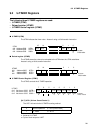
[bits 6, 5] (Reserved)
[bit 4] UTIE (U-TIMER Interrupt Enable)
UTIE specifies whether to enable an interrupt when the U-TIMER underflows.
1: Disable (initial value)
0: Enable
[bit 3] UNDR (UNDeR flow flag)
UNDR indicates that the U-TIMER has underflowed. An underflow interrupt occurs when
UNDR is set while "1" is set in UTIE. Resetting the register or writing "0" to the bit clears
UNDR. When the register is read by a read modify write instruction, "1" is always read from
the bit.
An attempt to write "1" to UNDR is ignored.
[bit 2] CLKS (clock select)
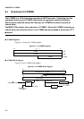
CLKS is a cascade specification bit for U-TIMER channels 0 and 1.
0: Use the peripheral clock (
φ
) as the clock source. (Initial value)
1: Use the underflow signal of channel 1 for the source clock timing of U-TIMER channel 0.
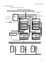
("f.f." in the block diagram)
CLKS is valid only for channel 0. Always set CLKS to "0" for channel 1.
[bit 1] UTST (U-TIMER STart]
UTST is the operation enable bit for the U-TIMER.
0: Stop. Writing "0" to this bit stops the U-TIMER even during operation. (Initial value)
1: Run: Writing "1" to this bit during operation continues operation.
[bit 0] UTCR (UTIMER CleaR)
Writing "0" to UTCR clears the U-TIMER to 0000
H
(also clears the flip-flop to 0).
"1" is always read from this bit.
<Notes>
• Asserting (starting) the start bit UTST in the stop state automatically causes reloading.
• Asserting the clear bit UTCR and start bit UTST simultaneously in the stop state clears the
counter to "0" and causes an underflow at the following count-down.
• Asserting the clear bit UTCR during operation clears the counter to "0" and may cause short
whisker-like pulses in the output waveforms, which may result in a UART or high-order U-
TIMER malfunction in cascade mode. When the output clock is used, do not assert the clear
bit during operation.
• If "0" or "1" is set in the low-order reload register (U-TIMER) in cascade mode, the timer does
not count normally.